TM 9--2350--292--20--2
0357 00--4
BRAKE LINKAGE ALIGNMENT, ADJUSTMENT AND BLEEDING
(NEW CONFIGURATION WITH BRAKE MODULATION) -- CONTINUED
0357 00
Alignment -- Continued
NOTE
Do not readjust linkage between the disc and the cylinder.
Linkage has been adjusted at the subassembly level for
proper clearance and should not be readjusted.
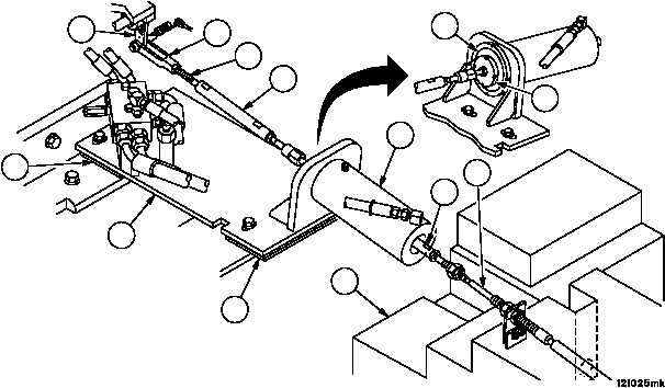
16. Ensure that disc (26) is resting against the face of the brake cylinder (27). Adjust rod assembly (19) until holes in
lever (20) and clevis (28) are aligned.
17. Connect rod assembly (19) to lever assembly (20) (WP 0367 00).
18. Temporarily remove restraint from lever.
19. Remove screws securing plate assembly (29) to vehicle (WP 0375 00).
CAUTION
If plate stack is too high or too low, ball swivel may reach
the extent of its 10 percent misalignment capability and
introduce binding, causing equipment damage or failure.
20. Adjust height of the front plate assembly (29) (remove or add plate (30) until linkage (31) moves freely without
binding).
21. Adjust height of the rear end of plate assembly (29) (remove or add plates (32) until brake cable (2) is optimized
within the fuel tank (33) and rod assembly (34) is optimized within the fuel tank (33) and rod assembly (34) is opti-
mized in the center of hollow in brake cylinder (27)).
22. Secure plate assembly (29) to vehicle (WP 0375 00).
23. Restraint parking brake pedal in “up” position.
24. Repeat steps 13 through 14. Torque nuts 15--20 lb--ft (20--27 NSm).
30
29
32
20
28
31
19
26
33
27
34
2
27