TM 9--2350--292--20--2
0357 00--6
BRAKE LINKAGE ALIGNMENT, ADJUSTMENT AND BLEEDING
(NEW CONFIGURATION WITH BRAKE MODULATION) -- CONTINUED
0357 00
Alignment -- Continued
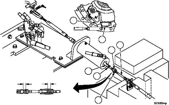
WARNING
A minimum thread engagement of 0.50 inch (12.7 mm)
between brake cable assembly and ball swivel must be
maintained at all times. Failure to comply could result in
assemblies separation, causing loss of vehicle service
brake, resulting in personnel injury or vehicle damage.
30. Verify thread engagement of 0.50 inch (12.7 mm) exists between ball joint (37) and threaded rod portion of brake
cable assembly (2). Torque nut (36) to 15--20 lb--ft (21--27 NSm).
31. Attach ball swivel (37) to rod assembly (38).
NOTE
Brake apply levers must remain resting against external
stops during this alignment or misalignment can occur.
The operator holds the brake pedal to the floor while the
maintainer checks the rear brake rod alignment marks
(black mark painted on the rod) aligns with the alignment
tabs.
32. With brake apply levers (7) resting against their external stops (9), adjust brake cable assembly (2) to remove all
slack from brake cable assembly (2) and rear brake linkage.
33. Verify a minimum of 0.50 inch (12.7 mm) thread engagement exists between threaded rod portion of ball swivel
(37) and rod assembly (38). Torque nut (35) to 15--20 lb--ft (20--27 NSm).
0.50 IN
(12.7 MM)
0.50 IN
(12.7 MM)
7
9
2
37
38
35
36