TM 9--2350--292--20--2
0359 00--1
NEUTRAL SAFETY SWITCH, STEERING CONTROL LOCK AND BRAKE
LOCK ADJUSTMENT (NEW CONFIGURATION WITH BRAKE MODULATION)
0359 00
THIS WORK PACKAGE COVERS:
Adjustment
INITIAL SETUP:
Tools and Special Tools
General mechanic’s tool kit (item 1, WP 0717 00)
Equipment Conditions
Vehicle parked on level surface with tracks blocked
(TM 9--2350--292--10)
Shifting control linkage adjusted (WP 0408 00)
Driver’s seat in stowed position
(TM 9--2350--292--10)
Subfloor plate #6 removed (WP 0454 00)
References
TM 9--2350--292--10
Adjustment
1. Turn vehicle MASTER switch ON.
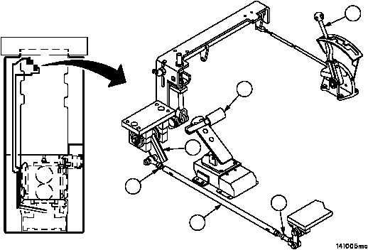
2. Place shift control lever (1) in PARK (P) position (TM 9--2350--292--10).
3. Push brake pedal (2) down as far as possible. Brake linkage (3) should lock in forward position.
4. If brake linkage (3) does not lock in forward position, loosen two nuts (4) on rod (5).
5. Adjust rod (5) until brake linkage (3) locks in forward position.
6. Place vehicle in neutral and release brake linkage (3). If brake linkage (3) does not release, adjust rod (5) until it
does.
7. Check that brake linkage (3) will lock and release properly. If brake linkage (3) operates properly, tighten two nuts
(4).
FORWARD
2
1
4
5
4
3