TM 9--2350--292--20--2
0360 00--2
HYDRAULIC BRAKE HOSE ASSEMBLY REPLACEMENT
(OLD CONFIGURATION) -- CONTINUED
0360 00
Hose Assembly
to be Replaced
Hose Assembly Location
From
To
Removal
Steps
Installation
Steps
12365278--89
Port INLET of pump and
motor assembly
Reservoir
1 -- 2
15 -- 18
12365278--90
Port OUTLET of pump
and motor assembly
Port PIN of power
boost manifold
3 -- 4
13 -- 14,
17 -- 18
12365278--91
Accumulator
Port ACC of power
boost manifold
5 -- 6
11 -- 12,
17 -- 18
12365278--94
Port A of modulation
valve
Hydraulic cylinder
7 -- 8
9 -- 10,
17 -- 18
12365278--92
Port T of modulation
valve
Port RIN of power
boost manifold
9 -- 10
7 -- 8,
17 -- 18
12365278--93
Port P of modulation
valve
Port POUT of power
boost manifold
11 -- 12
5 -- 6,
17 -- 18
12365278--95
Filter manifold tee
Port ROUT of power
boost manifold
13 -- 14
3 -- 4,
17 -- 18
12365278--142
Pressure switch
Port PS of power boost
manifold
15 -- 16
1 -- 2,
17 -- 18
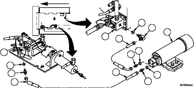
Removal
1. Remove one end of hose assembly (1), adapter (2) and preformed packing (3) from port INLET of pump and mo-
tor assembly (4). Discard preformed packing.
2. Remove other end of hose assembly (1), adapter (5) and preformed packing (6) from reservoir (7). Discard pre-
formed packing.
3. Remove one end of hose assembly (8), adapter (9) and preformed packing (10) from port PIN of power boost
manifold (11). Discard preformed packing.
4. Remove other end of hose assembly (8), adapter (12) and preformed packing (13) from port OUTLET of pump
and motor assembly (4). Discard preformed packing.
Figure 167
1
2
3
4
5
6
7
8
9
10
11
12
13
FORWARD
8