GOVERNORS
Speed Limits & Repair
If a Service Replacement Engine is used, check the top
governed speed using a tachometer, with the engine
operating on a completely assembled mower, to be sure
the blade tip speed will not exceed 19,000 feet per
minute. If necessary, change the governor spring or
adjust the top speed limit device, so the engine will not
exceed the recommended speed, based on blade length
as shown. See page 6 for adjustment procedure for
mechanical governor.
If a governor spring must be replaced, consult the
appropriate Illustrated Parts List. Choose the proper
governor spring by engine type number. AFTER A NEW
GOVERNOR SPRING IS INSTALLED, CHECK ENGINE
TOP GOVERNED SPEED WITH AN ACCURATE
TACHOMETER.
Run engine at half throttle to allow the engine to reach
normal operating temperature before measuring speed
with a tachometer. To account for tolerances, which may
be required by tachometer manufacturers, we suggest
that the top governed speed of the engine be adjusted at
least 200 R.P.M. lower than the maximum speeds
shown.
Since blade tip speed is a function of engine R.P.M.,
lower tip speeds require lower engine speeds.
The
chart
below
lists
various
lengths
of
rotary
lawnmower cutter blades, and the maximum blade
rotational speeds, which will produce blade tip speeds of
19, 000 feet per minute.
BLADE
MAXIMUM
LENGTH
ROTATIONAL R.P.M.
18"
4032
19"
3820
20"
3629
21"
3456
22"
3299
23"
3155
24"
3024
25"
2903
26"
2791
NOTE: For correct no load R.P.M. by model and type,
see engine sales manual. Note column.
MECHANICAL GOVERNOR
MODELS N, 6, 8 (CAST IRON)
Disassembly
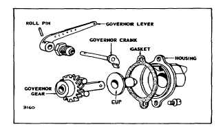
Loosen the two mounting screws to remove governor
housing. The cup can be pulled off the governor gear
and the gear will slide off the shaft.
See Fig. 4. To disassemble the governor crank, drive
the roll pin out at the end of the governor lever; remove
the governor crank bushing. Then pull governor crank
out of the housing.
Fig. 4. Governor Housing and Gear Assembly
Re-Assembly
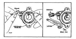
To assemble the governor crank, bushing and lever to
the housing, push the governor crank, lever end first, into
the housing. Slip the bushing onto the shaft:; then thread
the bushing into the housing and tighten securely. Place
the lever on the shaft with the governor crank in the
position shown in Fig. 5. Place the governor gear on
shaft in cylinder. Place gasket on governor housing;
then assemble governor housing to the cylinder and
tighten in place with two mounting screws.
Fig. 5 - Install Crank and Lever
2


