GOVERNORS
Repair & Adjustment
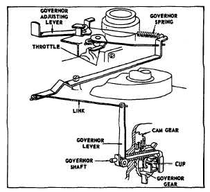
Fig. 15. Vertical Shaft
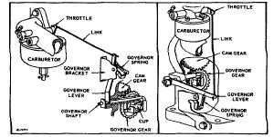
Fig. 16. Large Aluminum Engines
Re-Assembly
On horizontal crankshaft models, the governor rides on a
short stationary shaft and is retained by the governor
shaft, with which it comes in contact after the crankcase
cover is secured in place. Press governor cup against
crankcase cover to seat retaining ring on shaft, prior to
installing crankcase cover. It is suggested that the
assembly of the crankcase cover be made with the
crankshaft in a horizontal position. The governor shaft
should hang straight down parallel to the cylinder axis.
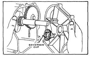
Fig. 17. If the governor shaft is clamped in an angular
position, pointing toward the crankcase cover, it is
possible for the end of the shaft to be jammed into the
inside of the governor assembly, resulting in broken
parts when the engine is started. After the crankcase
cover and gasket are in place, install cover screws. Be
sure that screw "A," Fig. 19, has nonhardening sealant
on threads of screw. Complete installation of remaining
governor linkages and carburetor and then adjust
governor shaft and lever.
Fig. 17. Showing Governor Shaft in Proper Position
On vertical crankshaft models the governor is part of the
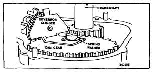
oil slinger and is installed as shown in Fig. 18. Models
100900 and 130900 use spring washer as shown in Fig.
18. Before installing sump be sure that governor cup is
in line with governor shaft paddle. Install sump cover
and gasket being sure screw "A," Fig. 19 has
nonhardening sealant on threads.
Fig. 18. Shows Spring on Camshaft after Governor is
Installed. Models 100900 and 130900 Only.
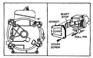
NOTE: On right angle auxiliary drive power take off
models, screw "A" does not need sealant but the four
screws holding the gear sump cover do need sealant.
See insert, Fig. 19.
Fig. 19. Sealant on Screw "A"
6