COMPRESSION
Valves & Guides
TABLE NO. 2
VALVE TAPPET CLEARANCE
MODEL SERIES
INTAKE
EXHAUST
ALUMINUM
MAX.
MIN.
MAX.
MIN.
CYLINDER
Milli-
Milli-
Milli-
Milli-
Inches
meter
Inches
meter
Inches
meter
Inches
meter
6B, 60000, 8B, 80000,
82000, 92000, 94000,
100000, 110000, 130000,
.007
0.18
.005
0.13
.011
0.28
.009
0.23
140000, 170000, 190000,
220000, 250000
Milli-
Milli-
Milli-
Milli-
CAST IRON CYLINDER
Inches
meter
Inches
meter
Inches
meter
Inches
meter
5, 6, 8, N, 9, 14, 19,
.009
0.23
.007
0.18
.016
0.41
.014
0.36
190000, 200000
23, 230000, 240000,
.009
0.23
.007
0.18
.019
0.48
.017
0.43
300000, 320000
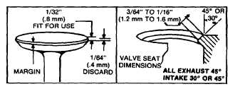
To Reface Valves and Seats
Faces on valves and valve seats should be resurfaced
with a valve grinder or cutter, to an angle of 45°. NOTE:
SOME ENGINE MODELS HAVE A 300 INTAKE VALVE
AND SEAT. Valve and seat should then be lapped with
a fine lapping compound to remove grinding marks and
assure a good seat. Valve seat width should be 3/64" to
1/16" (1.19-1.58 mm). Fig. 7. If the seat is wider, a
narrowing stone or cutter should be used. If either the
seat or valve is badly burned, it should be replaced.
Replace valve if margin is 1/64" (0.4 mm) or less after
refacing. Fig. 7.
Fig. 7 -- Valve and Seat Dimensions
To Check and Adjust Tappet Clearance
Insert the valves in their respective positions in the
cylinder. Turn the crankshaft to top dead center, end of
compression stroke. Both valves are now closed. Then
check clearance on the intake and exhaust valves with
feeler gauge. See Table 2. Grind off the end of the
valve stem if necessary, to obtain proper clearance.
CAUTION: Piston MUST be at top dead center at the
end of compression stroke to assure both valves being
closed.
NOTE: Check clearance cold.
To Install Valves
Some engines use the same spring for intake and
exhaust side, while others use a heavier spring on the
exhaust side. Compare springs before installing.
If retainers are held by a pin or collars, Fig. 2, Illus. 1 and
2, place valve spring and retainer (and cup on Model
Series 9, 14, 19, 20, 23, 24 and 32) into valve spring
compressor 19063. Compress the spring until it is solid.
insert the compressed spring and retainer (and cup when
used) into the valve chamber. Then drop the valve into
place, pushing the stem through the retainer. Hold the
spring up in the chamber, and the valve down. insert the
retainer pin with a needle nose pliers or place the collars
in the groove in the valve stem. Lower the spring until
the retainer fits around the pins or collars, then pull out
the spring compressor. Fig. 3. Be sure pin or collars
are in place.
If self-lock retainer, Fig. 2, Illus. 3, is used, compress
retainer and spring with compressor 19063. Large
diameter of retainer should be toward front of valve
chamber. Fig. 8. Insert compressed spring and retainer
into valve chamber. Drop the valve stem through larger
area of retainer slot and move the compressor so as to
center the small area of the valve retainer slot onto the
valve stem shoulder. Release the spring tension and
remove the compressor.
3