COMPRESSION
Valve Guides & Seat Inserts
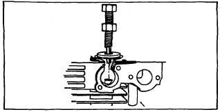
Fig. 10
Repairing Worn Aluminum or Sintered Iron Guides
Place piloted counterbore reamer, 19231, into worn
guide. Slide reamer guide, 19234, down shank of 19231
and center on valve seat, Fig. 9, Illus. 2. Place bushing
231218 next to reamer on reamer guide, Fig. 9, Illus. 2,
and mark reamer 1/16" (1.6 mm) above bushing.
Use Stanisol or kerosene to lubricate reamer while
turning clockwise. Continue reaming until mark on
reamer is flush with top of reamer guide bushing, 1-1/32"
(26.19 mm), Fig. 9, Illus. 3.
Installing Replacement Bushing
Clean out all chips. Place grooved end of service
bushing, 231218, into valve guide, Fig. 9, Illus. 4. Use
bushing driver, 19204, to press bushing into guide until
flush with top of guide or until it bottoms. Place reamer
guide bushing, 19234, on valve seat and slide finish
reamer, 19233, thru center of bushing. Fig. 9, Illus. 5.
Use Stanisol or kerosene as lubricant while turning
reamer clockwise. Continue reaming until reamer enters
tappet chamber. After reaming is done, continue to turn
reamer clockwise while removing. Clean out all chips
before reassembling engine.
Repairing Worn Valve Guides Using 19183 Reamer
and Reamer Guide Bushing 19192
Place piloted counterbore reamer, 19183 into worn
guide. Slide reamer guide bushing, 19192, down shank
of reamer and center in valve seat, Fig. 9, Illus. 2. Slide
replacement bushing, 230655, next to reamer shank on
reamer guide bushing. Mark reamer 1/16" (1.6 mm)
above bushing Fig. 9, Illus. 3. Use Stanisol or kerosene
to lubricate reamer while turning clockwise. Continue
reaming until mark on reamer is flush with top of
bushing. DO NOT REAM THROUGH THE WHOLE
GUIDE. Continue to turn reamer clockwise while
withdrawing reamer.
Installing Replacement Bushing 230655
Clean out all chips. Press in valve guide bushing,
230655, using bushing driver, 19204, until flush with top
of guide or until it bottoms. Fig. 9, Illus. 4. The bushing
230655 is finish reamed to size at the factory, no further
reaming is necessary, and a standard valve can be used.
NOTE: Cast iron engines use sintered (gray colored)
valve guide bushings. DO NOT REMOVE THESE
BUSHINGS. See reaming valve guide (230655 or
231218 bushing) to install service brass bushings.
CAUTION
Valve seating should be checked after bushing the
guide, and corrected if necessary by refacing the seat.
Valve Seat Inserts
Cast iron cylinder engines are equipped with an l exhaust
valve seat insert which can be removed and a new insert
installed. The intake side must be counterbored to allow
installation of an intake valve seat insert. Fig. 12, 13 &
14.
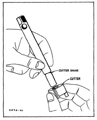
Fig. 12 - Inserting Cutter Shank
5


