GOVERNORS
Repair & Adjustment
Re-Assembly
Insert governor shaft into governor bushing from inside
cylinder. Then slide governor lever on governor shaft
and slide lever down onto shaft slot. Slide on lever
clamp and start screw in adjusting slot on clamp. Torque
lever clamp screw to 15 in. lbs. (.17 mkp, 1.7 N•m).
Install oil slinger and governor gear assembly, sump
gasket and oil sump. Place non-hardening sealant on
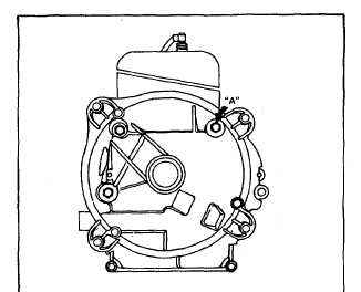
screw "A," Fig. 11, and tighten all sump screws.
Fig. 11 Sealant on Screw
Adjustment
Loosen lever adjusting screw, Fig. 10. While holding
governor lever and governor clamp to the left
(counterclockwise), tighten lever adjusting screw to 15 in.
lbs. (.17 mkp, 1.7 N•m).
Replacement, Governor Shaft Bushing
When a new governor shaft bushing is pressed in, it
should be pressed in until 1/16" (1.58 mm) extends out
from crankcase. Finish ream with 19058 reamer using
Stanisol or kerosene for lubricant.
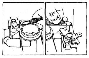
Installation, Governor Spring
Hold governor spring as shown in Fig. 12 with open end
of small loop down. Hook large loop in throttle link loop
as shown in Fig. 12 and pull loop toward throttle lever
until end of spring loop snaps on. Hook small loop in
throttle control lever as shown in Fig. 13.
Fig. 12. Installing
Fig. 13. Governor
Governor Spring
Spring Installed
100000, 130000, 140000, 170000, 190000, 220000 and
250000 (Aluminum Cylinders)
Disassembly
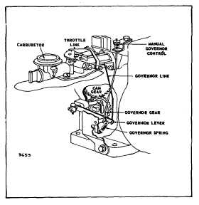
The governor used on the horizontal shaft models is
illustrated in Figs. 14 and 16. The governor used on the
vertical shaft models is incorporated with the oil slinger.
Figs. 15 and 16.
The only disassembly necessary is removing the
governor assembly as one unit from the shaft on the
crankcase cover on horizontal models. On vertical shaft
models, it is removed as part of the oil slinger. Further
disassembly is unnecessary.
Fig. 14. Horizontal Shaft
5