TM 9-2350-256-20-2
UNIT MAINTENANCE
RECOVERY VEHICLE, FULL TRACKED: MEDIUM, M88A1
NSN 2350-00-122-6826, EIC AQA
SHIFTING CONTROLS AND LINKAGES ALIGNMENT
ALIGNMENT, ADJUSTMENT
INITIAL SETUP:
Tools and Special Tools
References
Tool kit, general mechanic's (item 59, WP 0490 00)
Punches, drive (locating pins) (4) (item 43, WP 0490 00)
Equipment Condition
Powerplant removed (see WP 0098 00)
Materials/Parts
Batteries removed (see WP 0153 00)
Adhesive, rubber-base (item 3, WP 0489 00)
Transmission oil pressure checked
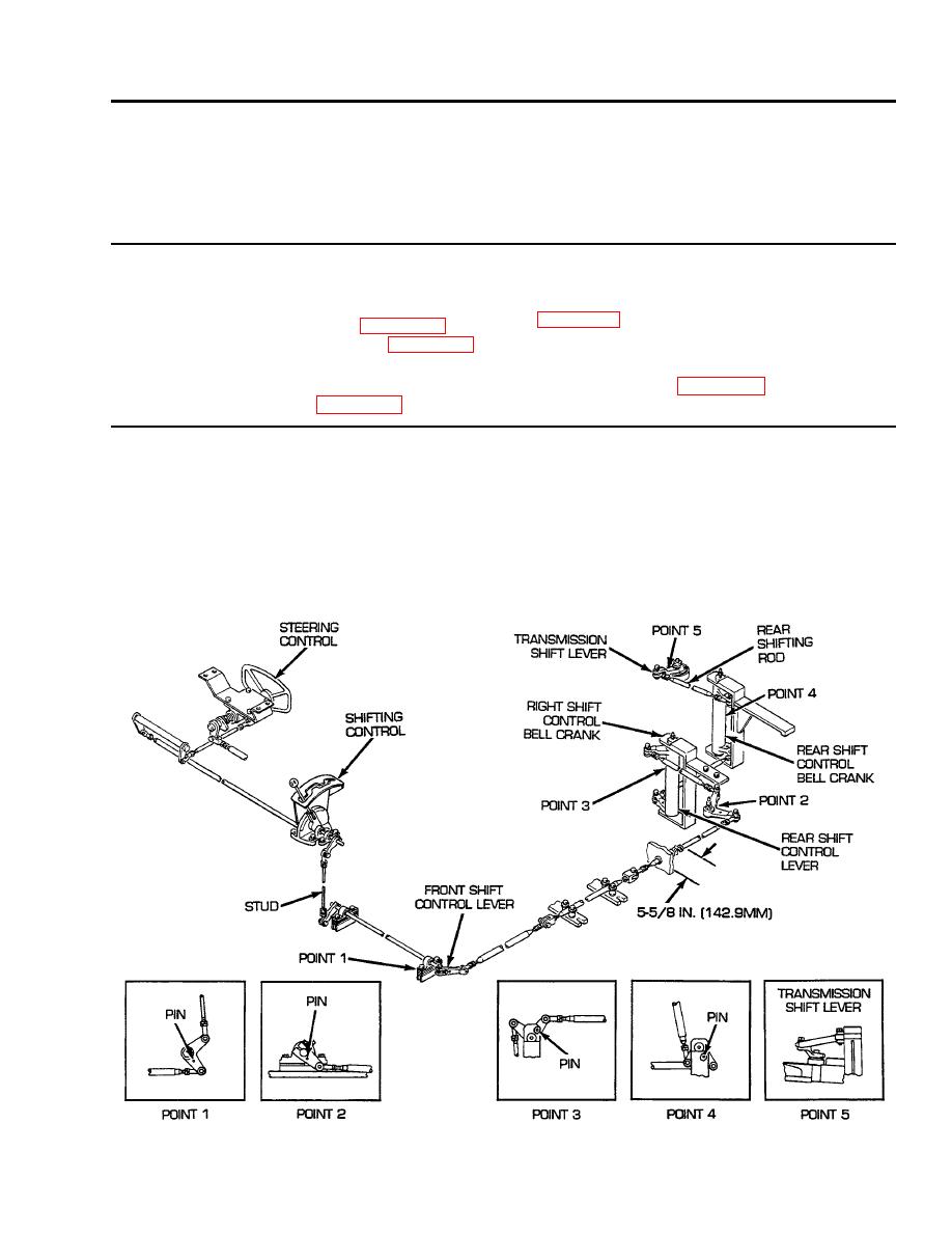
Alignment
1.
Disconnect rear shifting rod from transmission shift lever. Insert 1/8-in.- (3.2 mm-) diameter locating pin in front shift
control lever (point 1) and adjust stud until shifting control is in N (neutral) position.
2.
Insert locating pins in lever at points 2, 3, and 4. Adjust linkage between these points as necessary to permit pinning.
3.
Adjust rear shifting rod until rod clevis holes align with hole in transmission shift lever, when shifting position indicator on
transmission valve body is in N (neutral) position (point 5). Connect rod to lever.
4.
Extend rubber boot to 5-5/8 in. (142.9 mm). Cement rubber boot into bulkhead with adhesive and clamp rubber boot to rod.
Tighten all nuts and remove locating pins. Connect rear shifting rod to transmission shift lever.
0362 00-1


