SECTION V: TROUBLESHOOTING
TM 9-2350-256-20
WARNING
Remove all jewelry such as rings, dog tags,
bracelets, etc. If jewelry contacts a metal
surface a direct short may result in instant
heating of tools, damage to equipment,
and injury or death to personnel.
E
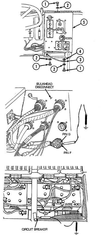
Reconnect switch panel to head lamps and bulkhead
wiring harness to main switch panel. Install main
switch panel (5), flat washer (4), ground lead (3), three
lockwashers (2), and three screws (1) to mounting
brackets. Open air inlet doors (TM 9-2350-256-10).
Disconnect bulkhead to master relay and left and right
taillight wiring harness from bulkhead disconnect.
Place red lead of multimeter on pin F of wire 400 and
black lead to ground. Turn MASTER switch on and
check for voltage. Turn MASTER switch OFF. Place
red lead of multimeter on pin G of wire 400 and black
lead to ground. Turn MASTER switch on and check for
voltage. Turn MASTER switch off. If voltage is
present replace/repair wire 459B of switch panel to
head lamps and bulkhead wiring harness (see
paragraph 6-52). If voltage in not present, go to step
F.
F
Reconnect bulkhead to master relay and left and right
taillight
wiring
harness
to
bulkhead
disconnect.
Disconnect wire 400 from bulkhead side of 30 ampere
(A) circuit breaker. Place red lead o multimeter on
terminal of circuit breaker and black lead to ground.
Turn MASTER switch on and check for voltage. Turn
MASTER switch off. If voltage i present, replace/repair
wire 400 of bulkhead to master relay and left and right
taillight wiring harness from 30 A circuit breaker to
bulkhead (see paragraph 6-71). If voltage is not
present, go to step G
2-63