SECTION V:
VEHICLE WIRING
TM 9-2350-256-20
b.
DISASSEMBLY
Disassemble wiring harness (see Chapter 6, Section VII).
c.
ASSEMBLY
Assemble wiring harness (see Chapter 6, Section VII).
d.
INSTALLATION
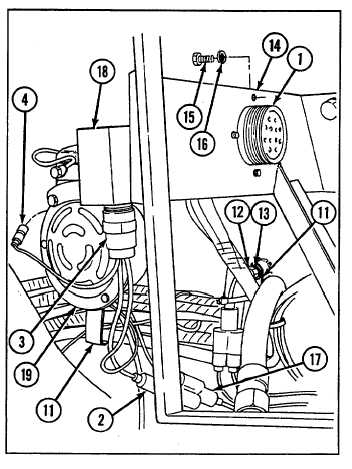
1
Connect two connectors (10 and 11) to switch panel to gage panel and miscellaneous switches wiring harness (28).
2
Connect connector (9) to power control switch (27).
3
Connect connectors (8) to fuel tank transmitter (26).
4
Install ground lead (7) using bolt (25).
5
Connect connector (6) to mechanical transmission low oil pressure switch (24).
6
Install connector (5) and new gasket (23) to bulkhead disconnect (20) using four screws (21) and four new
lockwashers (22).
7
Connect connector (4) to powerpack warning horn
assembly (19).
8
Connect connector (3) to powerpack warning horn (18).
9
Connect connector (2) to APU control box to foot
dimmer switch and bulkhead wiring harness (17).
10
Install connector (1) to gage panel bracket (14) using
four new lockwashers (16) and four screws (15).
11
Install 19 clamps (11) using new lockwasher (13) and
screw (12) for each.
NOTE
Follow-on maintenance:
Install air cleaner (see
paragraph 4-24)
6—
97