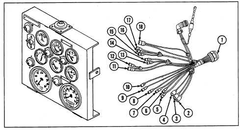
SECTION V: VEHICLE WIRING
TM 9-2350-256-20
b. DISASSEMBLY
Disassemble wiring harness (see Chapter 6, Section VII).
c. ASSEMBLY
Assemble wiring harness (see Chapter 6, Section VII).
d. INSTALLATION
1
Connect connector (18) to master warning light (30).
2
Connect connector (17) to fuel level gage (29).
3
Connect connector (16) to generator indicator (28).
4
Connect connector (15) to mechanical transmission oil pressure indicator light (27).
5
Connect two connectors (13 and 14) to transmission oil temperature gage (26).
6 Connect two connectors (11 and 12) to transmission oil pressure gage (25).
7
Connect two connectors (9 and 10) to engine oil pressure gage (24).
8
Connect two connectors (7 and 8) to engine oil temperature gage (23).
9
Connect two connectors (5 and 6) to fuel selector switch (22).
10 Connect three connectors (2, 3, and 4) to panel lights (21).
11 Install gage panel to mounting bracket (see paragraph 6-8).
NOTE
Follow-on maintenance:
Install gage panel if removed (see paragraph 6-8)
6-93


