SECTION II: HULL AND CAB COMPONENTS
4
Remove hinged rear fender (4) by removing eight
screws (13) and eight lockwashers (l4).
5
Remove rear fender (5) from support (15) by
removing two screws (16) and two lockwashers
(17).
NOTE
Any support (15) can be removed when
fenders on both sides of support have been
removed.
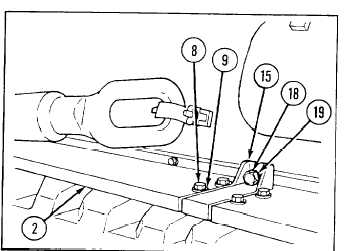
6
Remove five supports (15) by removing from each
screw (18) and lockwasher (19).
TM 9-2350-256-20
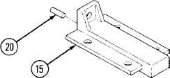
b. DISASSEMBLY
Remove five pins (20) from five supports (15).
c. ASSEMBLY
Install five pins (20) in five supports (15).
d. INSTALLATION
1
Install five supports (15) each with screw (18) and new lockwasher (19). Locate pins (20) in hull locating
holes.
2
Install rear fender (5) on support (15) with two new lockwashers (17) and two screws (16)
3
Install hinged rear fender (4) tvith eight screws (13) and eight new lockwashers (14).
4
Install splash guard (3) and strip (10) with five screws (11) and five new lockwashers (12).
5
Install each of four fenders (2) with eight screws (8) and eight new lockwashers (9).
6
Install front fender (1) with six screws (6) and six new lockwashers (7).
9 - 3 5