
TM 9-2350-256-34
0083 00
6.
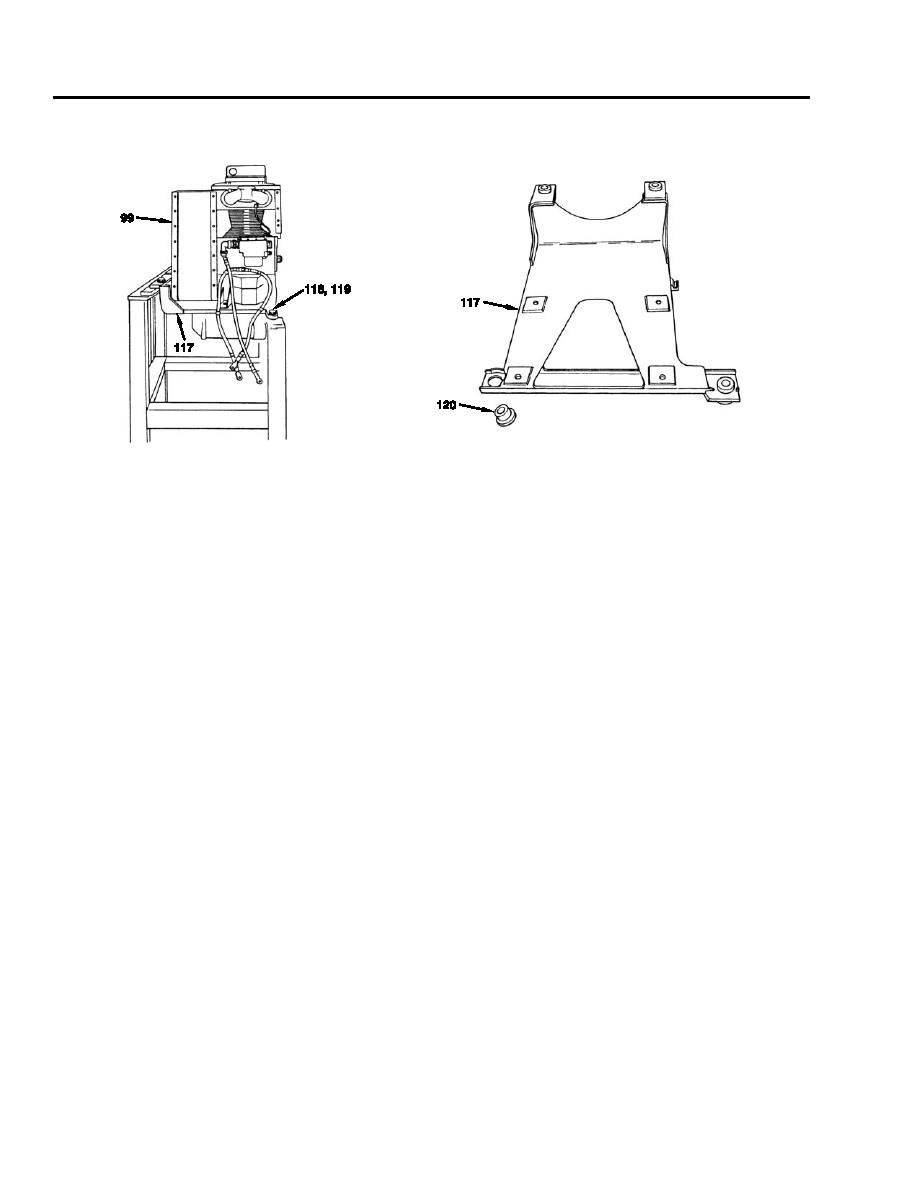
Install four mounts (120) to support (117).
7.
Install auxiliary engine (99), four lockwashers (119), and screws (118) to support (117).
NOTE
When replacing support (117), install drain tube (106) and position clamp (116) to support weight. Tap
10-32NF-28 hole in support.
8.
Install clamp (116), washer (115), and screw (114) to support (117).
9.
Install two side panels (113), short retainers (112), long retainers (111), 12 lockwashers (110), and screws (109).
10. Install name plate (108) and four screws (107).
11. Connect drain tube (106) and tighten nut (105).
12. Connect coupling half (104) and inverted flared tube connector (103).
13. Connect hose assembly (102) with bushing, coupling half, and retainer attached.
0083 00-18
