
TM 9-2350-256-34
0083 00
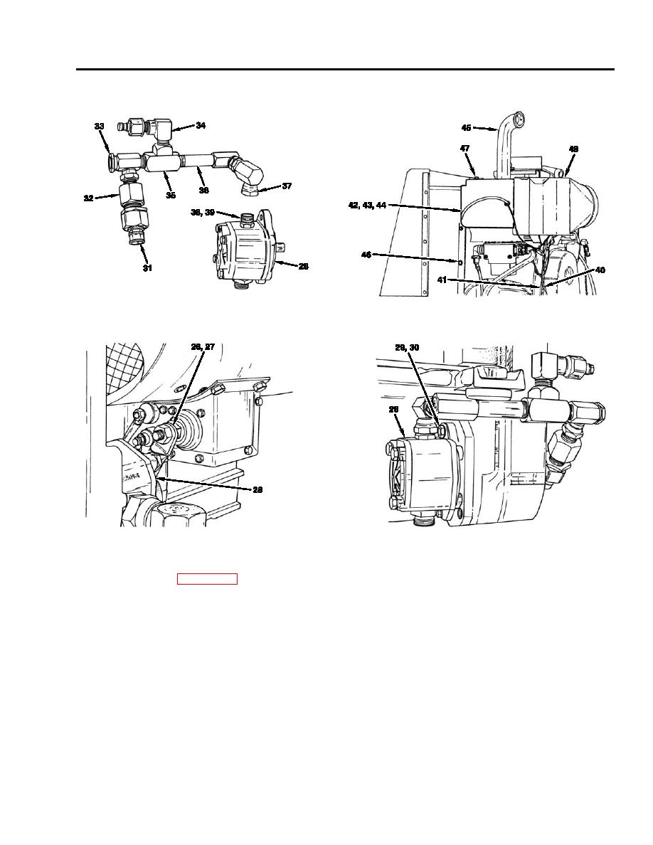
36. Install two packings (hidden) (39), adapter (38), two adapter unions (37), nipples (36), tee (35), elbow (34), valve (33),
adapter (32), and two coupling halves (31) to auxiliary hydraulic pump (28).
37. Install auxiliary hydraulic pump (28) with fittings attached, two lockwashers (30), and screws (29).
38. Position electrical cable (27) next to auxiliary hydraulic pump (28) and tighten terminal (26).
Test and Inspection
1.
All testing and adjusting of the APU must be accomplished with the unit outside the vehicle (groundhopping). A test stand
is required. Refer to WP 0088 00 for information on constructing a test stand to support the APU during groundhopping
tests.
2.
Fill chain case and crankcase to the proper levels in accordance with TM 9-2350-256-10 if required.
3.
Connect ground cable, cable assemblies, and hose assemblies provided for the test run outside the vehicle.
4.
Start auxiliary engine and allow a 3-minute warmup period with no load on the generator or pump. Then check the engine
speed with a hand tachometer or stroboscope. Adjust to 2000 100 rpm, if necessary, in the following manner:
a.
Locate the governor speed adjustment screw on the front of the engine
b.
Loosen locknut and turn screw slowly until tachometer or stroboscope reads 2000 100 rpm.
c.
Carefully tighten locknut so that the tachometer or stroboscope reading does not change.
5.
Stop engine, check crankcase oil, and fill to the proper levels in accordance with TM 9-2350-256-10 if required.
6.
Install a pressure gage in the gage port of the system selector valve relief valve, place the manual shutoff valve in NORMAL
OPERATION position, and place the system selector valve in AUXILIARY position.
0083 00-23
