TM 9--2350--292--20--1
0248 00--6
PERSONNEL HEATER CONTROL BOX ASSEMBLY REPAIR -- CONTINUED
0248 00
Assembly--Continued
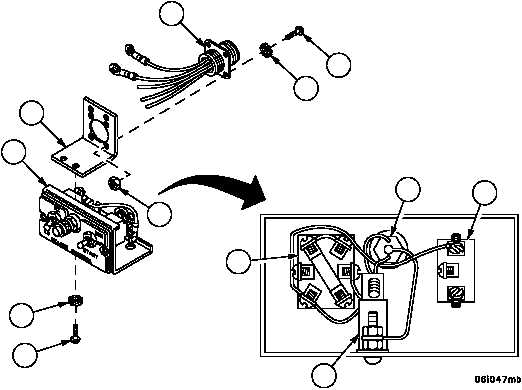
9. Connect indicator lamp assembly (29) to the following places:
4W191 Wire
Connect to Component
405
Pin 17 of Circuit Breaker (19)
407
Pin 19 of Heater Control Switch (28)
10. Install wiring harness 4W146 (25) in bracket (26) with four screws (23), four new lockwashers (24) and four nuts
(22).
11. Connect wiring harness 4W146 (25) to the following places:
4W146 Wire
Connect to Component
401
Pin 12 of Heater Switch (27)
402
Pin 14 of Heater Control Switch (28)
403
Pin 20 of Heater Control Switch (28)
405
Pin 17 of Circuit Breaker (19)
407
Pin 19 of Heater Control Switch (28)
12. Install bracket (26) and wiring harness 4W146 (25) on heater control box assembly lower half (9) with two screws
(20) and two new lockwashers (21).
Figure 68
26
25
24
23
21
20
9
29
27
19
28
22