TM 9--2350--292--20--1
0248 00--5
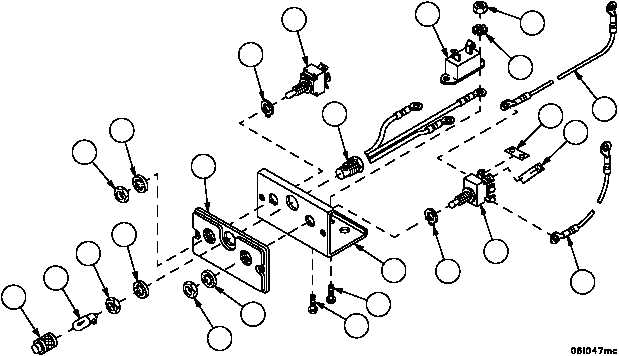
PERSONNEL HEATER CONTROL BOX ASSEMBLY REPAIR -- CONTINUED
0248 00
Assembly
NOTE
Refer to electrical schematic (FP--5) for internal wiring of
personnel heater control box assembly.
1. Install jumper (49) between pins 21 and 14 of heater control switch (28).
2. Install jumper (48) between pins 21 and 18 of heater control switch (28).
3. Install indicator lamp assembly (29) in face plate panel (47) and panel (39) with lockwasher (46), nut (45), lamp
(44) and lens (43).
4. Install heater control switch (28) in panel (39) with key washer (42), lockwasher (41) and nut (40).
5. Install heater switch (27) in panel (39) with key washer (38), lockwasher (37) and nut (36).
NOTE
After assembly, apply insulating varnish to all exposed
metal where wires attach to screw terminals to protect
against moisture and fungus growth.
6. Install circuit breaker (19) and ground wire of indicator lamp assembly (29) with screw (35), screw (34), new lock-
washer (33) and nut (32).
7. Connect cable assembly 4W147--1 (31) to pin 17 of circuit breaker (19) and pin 15 of heater control switch (28).
8. Connect cable assembly 4W147--2 (30) to pin 13 of heater switch (27) and pin 19 of heater control switch (28).
Figure 68
36
37
39
42
28
30
32
33
19
29
27
38
47
41
40
35
34
31
43
44
45
46
49
48