TM 9--2350--292--20--1
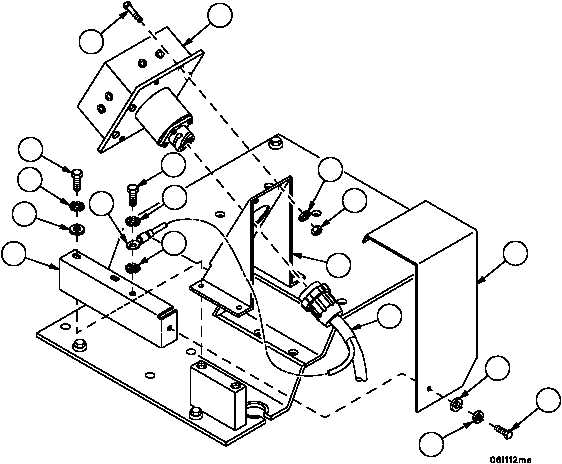
APU CONTROL BOX AND APU CONTROL BOX BRACKET REPAIR --
CONTINUED
0247 00
Installation
1. Install control box bracket (10), angle (15), flat washers (14) (if installed), terminal lug (13) with screws (11) and
new lockwashers (12).
2. Install control box assembly (5) on control box bracket (10) with four screws (4), four new lockwashers (8) and
four nuts (9). Do not tighten screws (4).
3. Connect wiring harness 4W700 connector P1 (7) to APU control box assembly (5).
4. Install cover (6) on control box assembly (5) with screw (1), new lockwasher (2) and flat washer (3). Tighten four
screws (4).
Figure 65
10
15
14
12
11
12
11
4
5
8
9
12
13
3
2
1
6
7
NOTE
FOLLOW--ON MAINTENANCE:
Install bleed valve manifold bracket and
brace, if removed (WP 0361 00)
Connect battery power (WP 0256 00)
END OF TASK
0247 00--9/10 blank