TM 9--2350--292--20--1
0247 00--7
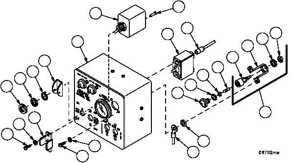
APU CONTROL BOX AND APU CONTROL BOX BRACKET REPAIR --
CONTINUED
0247 00
Assembly--Continued
5. Install socket (55), new lockwasher (54) and electrical bond nut (53) to retaining strap (56).
NOTE
Wiring harness 4W725 GND is secured to light assembly.
If wiring harness 4W725 is installed, only one screw and
lockwasher are required to install light assembly.
6. Install light socket assembly (52) on enclosure assembly (19) with new lockwasher (51), terminal (50), two screws
(48) and two new lockwashers (49), lamp (47), new gasket (46), new gasket (45) and lens (44).
7. Install two plugs (43) in switch assembly (42).
8. Install switch assembly (42), switch guard (41), tanged washer (40), lockwasher (39) and nut (38) on enclosure
assembly (19).
9. Install lead assembly 4W123--3 (37) to fuel shutoff switch (36).
10. Install fuel shutoff switch (36) on enclosure assembly (19) with switch guard (35), two screws (33) and two new
lockwashers (34).
Figure 66
51
50
47
46
45
44
36
37
48
49
33
34
35
38
39
40
41
19
42
43
53
54
56
55
52