TM 9--2350--292--20--1
0247 00--3
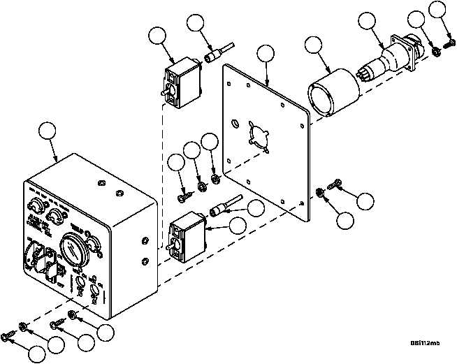
APU CONTROL BOX AND APU CONTROL BOX BRACKET REPAIR --
CONTINUED
0247 00
Disassembly
1. Remove four screws (16), four lockwashers (17) and lift rear panel (18) gently from enclosure assembly (19). Dis-
card lockwashers.
2. Remove four screws (20), four lockwashers (21) and wiring harness 4W725 (22) from extension (23) on rear pan-
el (18). Discard lockwashers.
3. Disconnect wiring harness 4W725 (22) connectors from enclosure assembly (19) in accordance with Electrical
Schematic (FP--7) and remove from enclosure assembly (19).
4. Remove four screws (24), four lockwashers (25), four flat washers (26) and extension (23) from rear panel (18).
5. Remove four screws (27), four lockwashers (28) and two toggle switches (29 and 30) from enclosure assembly
(19). Discard lockwashers.
6. Remove lead assembly 4W123--1 (31) from preheat switch (29) and lead assembly 4W123--2 (32) from start
switch (30).
Figure 66
27
27
28
28
19
18
23
22
21
20
16
17
24
2526
29
31
32
30