TM 9--2350--292--20--1
0247 00--6
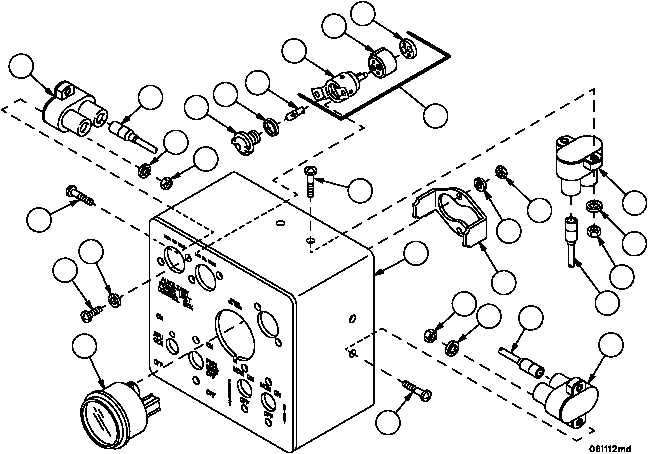
APU CONTROL BOX AND APU CONTROL BOX BRACKET REPAIR --
CONTINUED
0247 00
Assembly
1. Install three circuit breakers (73), lead assembly 4W123--3 (37), lead assembly 4W123--1 (31), and lead assembly
4W123--2 (32), six new lockwashers (72), six nuts (71) and six screws (70) to enclosure assembly (19).
2. Install pressure indicator (69), pressure indicator mount (68), two lockwashers (67) and two nuts (66) to enclosure
assembly (19).
NOTE
There are two warning light assemblies. Perform steps 3
and 4 to assemble one warning light assembly.
3. Install shell receptacle (64) and retainer (63) on warning light socket (65).
4. Install warning light socket assembly (62) on enclosure assembly (19) with two screws (60), two new lockwashers
(61), lamp (59), new gasket (58) and lens (57).
Figure 66
73
37
72
71
57
58
59
65
64
63
62
70
70
61
60
69
19
70
7172
32
73
31
71
72
73
66
67
68