TM 9--2350--292--20--1
0071 00--6
SIGNALS FROM SENSOR IS BELOW ITS VALID RANGE, INDICATES BOTH
CIRCUITS ARE OPEN, IS ABOVE ITS VALID RANGE, INDICATES CIRCUITS
ARE CLOSED, OR WAS NOT PROCESSED CORRECTLY -- CONTINUED
0071 00
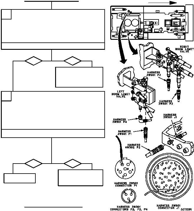
1. Reconnect wiring harness 4W502 connector
P1 to remote terminal unit connector J1.
2. Disconnect wiring harness 3W501 from sensor
that is failing (WP 0677 00).
3. Use table in step D to conduct a continuity
check of wiring harness 3W501 wires that
correspond to the sensor that is failing.
E
CONTINUED ON NEXT PAGE
CONTINUED FROM STEP D
Is continuity present?
yes
no
Repair (WP 0290 00) or
replace (WP 0677 00)
wiring harness 3W501.
Verify fault is corrected.
1. Replace sensor that is failing (WP 0691 00).
2. Reconnect wiring harness 4W502 connector
P2 to wiring harness 3W501 connector J1
(WP 0678 00).
3. Reconnect wiring harness 3W501 to sensor, if
removed (WP 0677 00).
4. Start Enhanced Diagnostics program
(WP 0086 00) and run selftest.
F
Does failing sensor now pass selftest?
yes
no
Replace remote termi-
nal unit (WP 0675 00).
Verify fault is corrected.
Fault corrected.
FORWARD