TM 9--2350--292--20--1
0071 00--8
SIGNALS FROM SENSOR IS BELOW ITS VALID RANGE, INDICATES BOTH
CIRCUITS ARE OPEN, IS ABOVE ITS VALID RANGE, INDICATES CIRCUITS
ARE CLOSED, OR WAS NOT PROCESSED CORRECTLY -- CONTINUED
0071 00
CONTINUED FROM STEP F
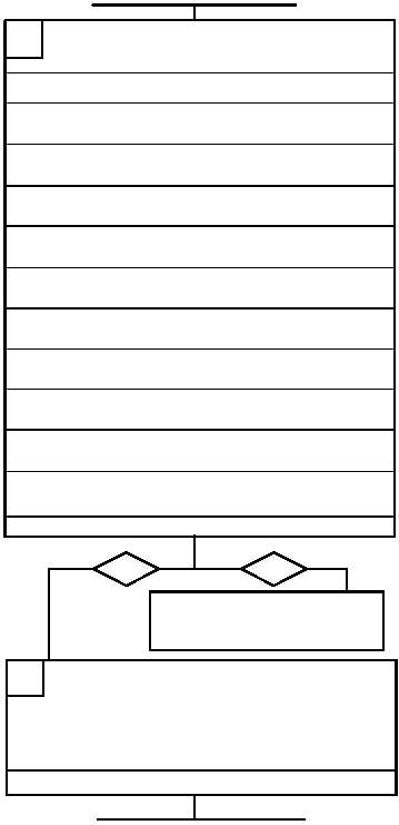
3. Use the following table to conduct a continuity
check of wiring harness 4W506 wires that
correspond to the sensor that is failing.
G
CONTINUED ON NEXT PAGE
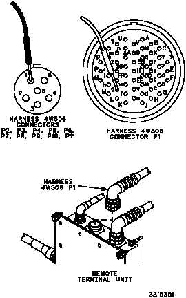
Sensor
Wiring Harness 4W506
Remote Terminal
Connectors
Connector
4MT514
P10--1
P1--g
P10--2
P1--h
J5
P10--3
P1--I
4MT515
P9--1
P1--d
P9--2
P1--e
J5
P9--3
P1--f
4MT516
P8--1
P1--a
P8--2
P1--b
J5
P8--3
P1--c
4MT517
P6--1
P1--W
P6--2
P1--X
J5
P6--3
P1--Y
4MT518
P5--1
P1--T
P5--2
P1--U
J5
P5--3
P1--V
4MT519
P4--1
P1--P
P4--2
P1--R
J5
P4--3
P1--S
4S520
P11--A
P1--w
P11--B
P1--x
J5
P11--C
P1--y
4MT521
P7--1
P1--K
P7--2
P1--L
J5
P7--3
P1--M
4MT522
P3--1
P1--G
P3--2
P1--H
J5
P3--3
P1--J
4MT523
P2--1
P1--D
P2--2
P1--E
J5
P2--3
P1--F
Is continuity present?
1. Replace sensor that is failing (WP 0684 00).
2. Reconnect wiring harness 4W506 to sensor
and remote terminal unit connector J5
(WP 0681 00).
3. Start Enhanced Diagnostics program
(WP 0086 00) and run selftest.
H
Does failing sensor now pass selftest?
yes
no
Repair (WP 0290 00) or replace
(WP 0681 00) wiring harness
4W506. Verify fault is corrected.