TM 9--2350--292--20--1
0071 00--5
SIGNALS FROM SENSOR IS BELOW ITS VALID RANGE, INDICATES BOTH
CIRCUITS ARE OPEN, IS ABOVE ITS VALID RANGE, INDICATES CIRCUITS
ARE CLOSED, OR WAS NOT PROCESSED CORRECTLY -- CONTINUED
0071 00
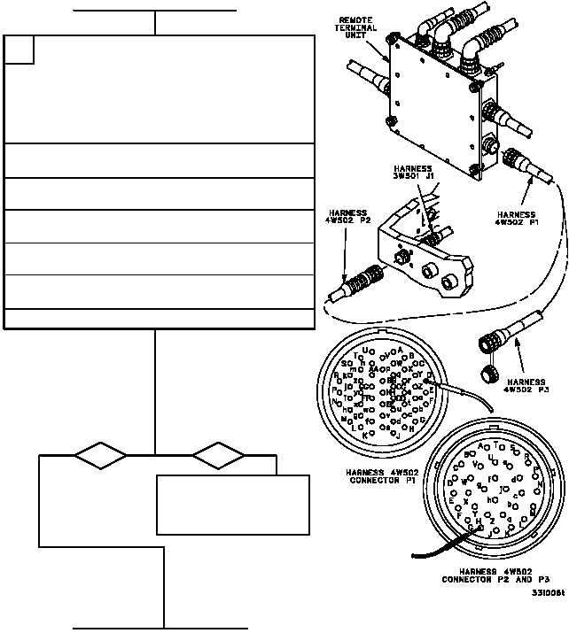
1. Disconnect wiring harness 4W502 connector
P1 from remote terminal unit connector J1.
2. Disconnect wiring harness 4W502 connector
P2 from wiring harness 3W501 connector J1
(WP 0678 00).
3. Use the following table to conduct a continuity
check of wiring harness 4W502 wires that
correspond to the sensor that is failing.
D
CONTINUED ON NEXT PAGE
CONTINUED FROM STEP NO TAG
Is continuity present?
yes
no
Repair (WP 0290 00) or
replace (WP 0678 00)
wiring harness 4W502.
Verify fault is corrected.
Remote
Sensor
Wiring Harness
Wiring Harness
Terminal
3W501 Connectors
4W502 Connectors Connector
3S510
P2--A
J1--a
P2--a
P1--w
P2--B
J1--b
P2--b
P1--x
J1
P2--C
J1--c
P2--c
P1--y
3S511
P3--A
J1--d
P2--d
P1--z
P3--B
J1--e
P2--e
P1--AA
J1
P3--C
J1--f
P2--f
P1--BB
3S512
P4--A
J1--g
P2--g
P1--CC
P4--B
J1--h
P2--h
P1--DD
J1
P4--C
J1--j
P2--j
P1--EE
3MT513
P1--1
J1--H
P2--H
P1--D
P1--2
J1--J
P2--J
P1--E
J1
P1--3
J1--K
P2--K
P1--F