TM 9--2350--292--20--1
EXHAUST SMOKE GENERATING SYSTEM OVERVIEW AND DIAGRAMS.
0072 00
THIS WORK PACKAGE COVERS:
Exhaust Smoke Generating System Overview And Diagrams.
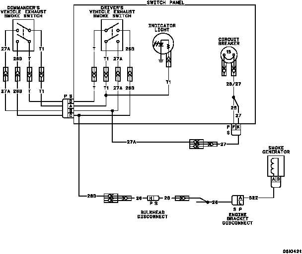
The exhaust smoke generating system consists of the commander’s VEHICLE EXHAUST SMOKE switch, the driv-
er’s EXHAUST SMOKE switch, EXHAUST SMOKE indicator light, 15--amp circuit breaker, two smoke generators
and associated electrical wiring.
When the main engine is running (1600 rpm and above), the exhaust smoke generating system is put in operation
when either the commander’s VEHICLE EXHAUST SMOKE switch or the driver’s EXHAUST SMOKE switch is
turned ON. Operating voltage (+28 V dc) is supplied from the main engine generator output system through one or
the other of the EXHAUST SMOKE switches to the smoke generators. The VEHICLE EXHAUST SMOKE indica-
tor on the switch panel lights when either of the exhaust smoke switches is set to the ON position. System power
(+24 -- 28 V dc) is supplied from the master relay circuits through the 15--amp circuit breaker and applicable switch
to the indicator.
The relationship of the components of the exhaust smoke generating system are shown below.
END OF TASK
0072 00--1/2 blank