TM 9--2350--292--20--2
0624 00--3
AUXILIARY POWER UNIT ENGINE SHROUDS REPLACEMENT --
CONTINUED
0624 00
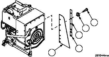
Removal--Continued
NOTE
The following steps are performed with APU engine as-
sembly removed from vehicle (WP 0586 00) and mounted
on APU test stand.
5. Remove six screws (18), six lockwashers (19), right side panel (20) and retaining strips (21 and 22). Discard lock-
washers.
Figure 341
18
19
20
21
22
6. Inspect parts for damage and replace as required.
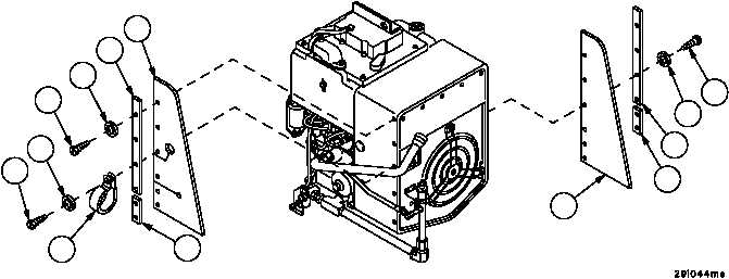
Installation
1. Install right side panel (20) and retaining strips (21 and 22) with six screws (18) and six new lockwashers (19).
2. Install left side panel (15) and retaining strips (16 and 17) with five screws (13) and five new lockwashers (14).
3. Install clamp (11) over oil filler tube and assemble to retaining strip (17) and panel (15) with screw (9) and new
lockwasher (10).
Figure 341
18
19
20
21
22
9
10
11
13
14
15
16
17