TM 9--2350--292--20--2
0624 00--2
AUXILIARY POWER UNIT ENGINE SHROUDS REPLACEMENT --
CONTINUED
0624 00
Removal--Continued
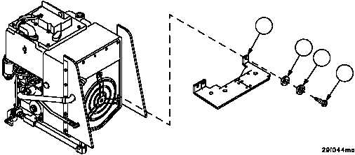
2. Remove three screws (5), three lockwashers (6), three flat washers (7) and bottom panel (8). Discard lockwashers.
Figure 341
5
6
7
8
NOTE
The following steps are performed with APU cover re-
moved (WP 0413 00) and engine deck access door
opened (adjacent to the APU) (TM 9--2350--292--10).
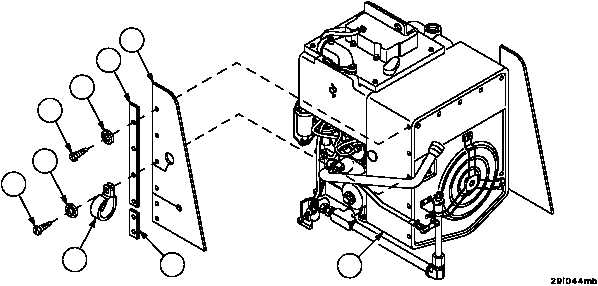
3. Remove screw (9), lockwasher (10) and clamp (11) on left hand side (the side towards rear of vehicle) of APU
engine assembly (12). Remove clamp (11) from oil filler tube. Discard lockwasher.
4. Remove remaining five screws (13), five lockwashers (14), left side panel (15) and retaining strips (16 and 17).
Discard lockwashers.
Figure 341
9
10
11
12
13
14
15
16
17