TM 9--2350--292--20--2
0363 00--1
BRAKE ROD ASSEMBLY 12366874 REPAIR (OLD CONFIGURATION)
0363 00
THIS WORK PACKAGE COVERS:
Removal, Disassembly, Assembly, Installation
INITIAL SETUP:
Tools and Special Tools
General mechanic’s tool kit (item 1, WP 0717 00)
Materials/Parts
Cotter pins (2) (item 17, WP 0718 00)
Equipment Conditions
Vehicle parked on a level surface with tracks blocked
(TM 9--2350--292--10)
Vehicle MASTER switch OFF (TM 9--2350--292--10)
Subfloor plates #6 and #13 removed (WP 0454 00)
Brake pedal released (TM 9--2350--292--10)
Driver’s seat in stowed position and driver’s hatch
opened (TM 9--2350--292--10)
Accelerator linkage removed as required
(WP 0226 00)
References
TM 9--2350--292--10
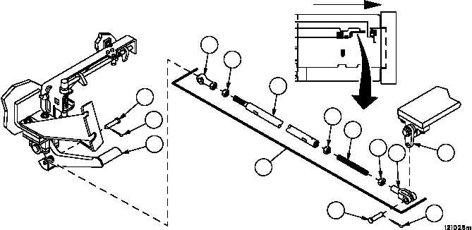
Removal
1. Remove cotter pin (1), headed straight pin (2) and rod assembly (3) from brake pedal and bracket assembly (4).
Discard cotter pin.
2. Remove cotter pin (5), headed straight pin (6) and rod assembly (3) from lever (7). Discard cotter pin.
Disassembly
1. Loosen nut (8), remove rod end bearing (9) and nut (8) from rod assembly (3).
2. Loosen nut (10), remove rod end clevis (11) and nut (10) from stud (12).
3. Loosen nut (13) and remove stud (12) and nut (13) from rod (14).
4. Remove nut (13) from stud (12).
5. Inspect parts for damage and replace as required.
Figure 168
1
4
5
6
7
FORWARD
11
2
9
8
12
10
3
14
13