TM 9--2350--292--20--2
0365 00--1
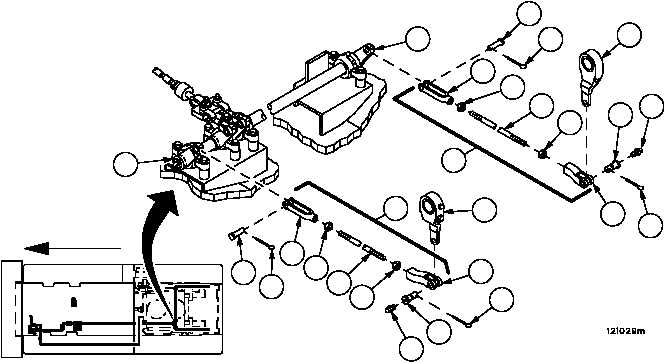
BRAKE ROD ASSEMBLIES 12364827--2 REPAIR
0365 00
THIS WORK PACKAGE COVERS:
Removal, Disassembly, Assembly, Installation
INITIAL SETUP:
Tools and Special Tools
General mechanic’s tool kit (item 1, WP 0717 00)
Materials/Parts
Cotter pins (4) (item 17, WP 0718 00)
Lubricant (item 3, WP 0716 00)
Equipment Conditions
Vehicle parked on a level surface with tracks blocked
(TM 9--2350--292--10)
Powerpack removed (WP 0188 00)
References
TM 9--2350--292--10
NOTE
This procedure applies to both the left and right hand rod
assemblies.
Removal
1. Remove cotter pin (1), straight pin (2) with lubrication fitting (3) and rod assembly (4) from brake apply lever (5).
Discard cotter pin.
2. Remove lubrication fitting (3) from straight pin (2).
3. Remove cotter pin (6), straight pin (7) and rod assembly (4) from lever assembly (8). Discard cotter pin.
Disassembly
1. Loosen two nuts (9), remove two rod end clevises (10 and 11) and two nuts (9) from rod (12).
2. Inspect parts for damage and replace as required.
Figure 169
FORWARD
1
2
3
4
4
5
6
7
9
11
12
10
9
1
2
3
5
6
7
9
9
12
11
10
8
8