TM 9--2350--292--20--2
0364 00--2
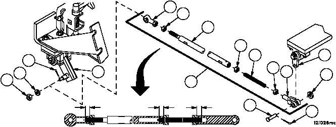
BRAKE ROD ASSEMBLY 12366874 REPAIR (NEW CONFIGURATION WITH
BRAKE MODULATION) -- CONTINUED
0364 00
Assembly
NOTE
A minimum of 0.62 inch (15.7 mm) must be maintained
between face of nuts and end of rod assembly.
1. Install nut (15) on stud (14).
2. Install stud (14) with nut (15) on rod (16). Do not tighten nut (15).
3. Install nut (12) and rod end clevis (13) on stud (14). Do not tighten nut (12).
4. Install nut (10) and rod end bearing (11) on rod assembly (4). Do not tighten nut (10).
Installation
WARNING
Adjustment to length of rod assemblies must be accom-
plished by adjusting both rod end clevises evenly. Rod
end clevises must maintain a minimum of 0.62 inch (15.7
mm) thread engagement from end of rod assemblies at
all times. Failure to comply could result in rod assembly
separation causing loss of vehicle service brake, resulting
in personnel injury or equipment damage.
1. Adjust rod end bearing (11), rod end clevis (13) and stud (14) on rod assembly (4) until headed straight pin (8) can
be freely installed in lever (9) and rod end bearing (11) can be attached to lever (5).
2. Install headed straight pin (8), washer (7) and a new cotter pin (6) to attach clevis (13) to lever (9).
3. Install flat washer (3), nut (2) and cotter pin (1) to attach rod end bearing (11) to lever (5).
4. Tighten three nuts (10, 12 and 15).
5. Perform brake linkage alignment (WP 0357 00).
6. Adjust brake locking rod (WP 0359 00).
0.62 IN
(15.7 MM)
0.62 IN
(15.7 MM)
0.62 IN
(15.7 MM)
5
1
3
2
11
10
16
4
8
7
9
15
14
12
13
6
NOTE
FOLLOW--ON MAINTENANCE:
Install accelerator linkage as required (WP 0226 00)
Install subfloor plates #6 and #13 (WP 0454 00)
END OF TASK