TM 9--2350--292--20--2
0365 00--2
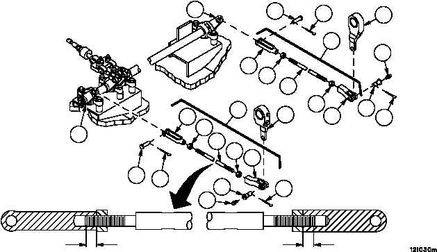
BRAKE ROD ASSEMBLIES 12364827--2 REPAIR -- CONTINUED
0365 00
Assembly
NOTE
Nuts must be installed on rods with a minimum thread
length of 0.62 inch (15.7 mm) between face of nuts and
end of rod.
Install two nuts (9) and two rod end clevises (10 and 11) on rod (12). Do not tighten nuts.
Installation
1. Install lubrication fitting (3) in straight pin (2).
WARNING
Adjustment to length of rod assemblies must be accom-
plished by adjusting both rod end clevises evenly. Rod
end clevises must maintain a minimum of 0.62 inch (15.7
mm) thread engagement from end of rod assemblies at
all times. Failure to comply could result in rod assembly
seWPtion causing loss of vehicle service brake, resulting
in personnel injury or equipment damage.
2. Adjust rod end clevises (10 and 11) equally on rod assembly (4) until two straight pins (2 and 7) can be freely in-
serted into clevises (10 and 11) and levers (5 and 8).
3. Install straight pin (2) with lubrication fitting (3) and straight pin (7).
4. Install two new cotter pins (1 and 6).
5. Tighten two nuts (9) against two rod end clevises (10 and 11).
6. Lubricate rod assembly (4) (WP 0187 00).
Figure 169
8
7
6
5
4
4
3
2
1
9
9
10
11
12
1
2
3
5
6
7
8
9
9
10
11
12
0.62 IN
(15.7 MM)
0.62 IN
(15.7 MM)
NOTE
FOLLOW--ON MAINTENANCE:
Install powerpack (WP 0188 00)
Perform brake linkage adjustment (WP 0356 00 or
WP 0355 00)
END OF TASK