TM 9--2350--292--20--2
0367 00--4
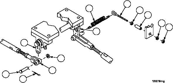
BRAKE SHAFT ASSEMBLY 12364824 AND BRAKE PEDAL RETURN SPRING
REPLACEMENT (NEW CONFIGURATION WITH BRAKE MODULATION) --
CONTINUED
0367 00
Installation--Continued
7. Connect spring (1) to lever (6).
NOTE
Nut must be tight against end of threaded portion of eye
bolt prior to installation of support tube.
8. Install nut (7) and tube support (4) on eyebolt (5).
9. Connect spring (1) to eyebolt (5).
10. Install eyebolt (5), nut (7) and tube support (4) in vehicle bracket with new lockwasher (3) and nut (2).
11. Tighten nut (7) against vehicle bracket to secure eyebolt (5) in place.
12. Install rod assembly (15) on lever (16) with straight headed pin (14), washer (13) and new cotter pin (12).
13. Perform brake linkage alignment (WP 0357 00).
14. Adjust brake pedal locking rod (WP 0359 00).
1
2
3
7
4
5
6
13
16
14
15
12
NOTE
FOLLOW--ON MAINTENANCE:
Install subfloor plates #6, #13 and #16, if removed
(WP 0454 00)
END OF TASK