TM 9--2350--292--20--2
0394 00--6
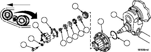
IDLER HUB ASSEMBLY REPAIR -- CONTINUED
0394 00
Installation
1. Recheck position of new preformed packing (13) on idler arm assembly (10) and install hub assembly (6).
2. Install bearing (12) and adjusting nut (11) on idler arm assembly (10).
3. Torque adjusting nut (11) to 35--40 lb--ft (48--54 NSm) (item 2, WP 0717 00) while rotating hub assembly (6) in both
clockwise and counter--clockwise directions.
4. Recheck torque adjusting nut (11) to 35--40 lb--ft (48--54 NSm) (item 2, WP 0717 00) to insure bearings have
seated.
5. Loosen adjusting nut (11), torque adjusting nut (11) to 50 lb--in (5.7 NSm) (item 21, WP 0717 00). No end play
should be present. If end play is present, repeat Installation steps 3 through 5.
6. Install flat washer (9), bearing nut lock (7) and bearing nut (8) on idler arm assembly (10). Reverse flat washer (9)
if necessary to index pin.
CAUTION
Improper torque could affect the bearing adjustment and
cause equipment damage.
7. Torque nut (8) to 120--125 lb--ft (162.12--169 NSm) (item 2, WP 0717 00).
8. Bend one end of bearing nut lock (7) over the flat of nut (8).
9. Install spring (5), new gasket (4) and access cover (3) to hub assembly (6) with six screws (1) and six new lock-
washers (2).
Figure 186
FORWARD
1
2
3
4
5
8
9
11
7
12
6
10
ARMOR SKIRTS
REMOVED
FOR CLARITY
13