TM 9--2350--292--20--2
0394 00--5
IDLER HUB ASSEMBLY REPAIR -- CONTINUED
0394 00
Assembly -- Continued
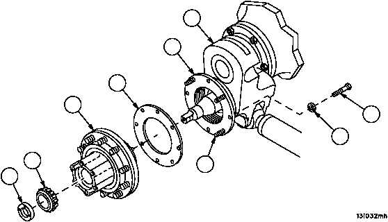
13. Install gasket (16) and hub assembly (6) on idler arm assembly (10) spindle and mate to seal assembly (17).
14. Install outer bearing (12) and adjusting nut (11) on idler arm assembly (10) temporarily for support.
15. Align and tighten four screws (14) to secure seal assembly (17) and gasket (16) to hub assembly (6).
16. Remove adjusting nut (11) and outer bearing (12) from idler arm assembly (10).
17. Remove hub assembly (6) from idler arm assembly (10) spindle. Install remaining four screws (14) and four new
lockwashers (15). Torque screws to 20 -- 35 lb--ft (27.1 -- 47.5 N•m).
Figure 186
11
12
10
15
14
17
16
14
6