TM 9--2350--292--20--2
ADJUSTING LINK AND COMPONENTS REPAIR (NEW CONFIGURATION) –
CONTINUED
0393 00
Installation
NOTE
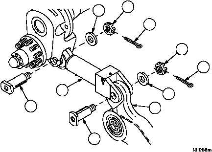
Link assemblies must be installed in front suspension as-
sembly so that clevis--end grease fitting is facing out-
board.
1. Apply anti--seize compound to shaft and threads of clevis pins (8 and 2) prior to installation.
2. Install end of adjusting link (5) to vehicle with clevis pin (8), flat washer (10) and nut (9).
3. Install new cotter pin (7) in clevis pin (8).
4. Connect the other end of adjusting link (5) to hub and arm assembly (6) with clevis pin (2), flat washer (4) and nut
(3).
5. Install new cotter pin (1) in clevis pin (2).
Figure 184A
2
4
5
6
7
8
9
10
1
3
NOTE
FOLLOW--ON MAINTENANCE:
Install idler hub assembly (WP 0394 00)
Install lower armor skirt panel #1 support
(WP 0442 00)
END OF TASK
0393 00--5/6 blank