TM 9--2350--292--20--2
0393 00--1
ADJUSTING LINK AND COMPONENTS REPAIR (NEW CONFIGURATION)
0393 00
THIS WORK PACKAGE COVERS:
Removal, Disassembly, Assembly, Installation
INITIAL SETUP:
Tools and Special Tools
General mechanic’s tool kit (item 1, WP 0717 00)
Slide puller (item 46, WP 0717 00)
Mechanical Puller (item 49, WP 0717 00)
Torque wrench (item 2, WP 0717 00)
Electrical heat gun (item 34, WP 0717 00)
Materials/Parts
Cotter pins (2) (item 107, WP 0718 00)
Preformed packing (item 450, WP 0718 00)
Preformed packing (item 458, WP 0718 00)
Preformed packing (item 459, WP 0718 00)
Dry--cleaning solvent (item 1, WP 0716 00)
Materials/Parts -- Continued
Sleeving insulation (item 401, WP 0718 00)
Sealing compound (item 30, WP 0716 00)
Anti--seize compound (item 90, WP 0716 00)
Lubricant (item 3, WP 0716 00)
Wiping rags (item 7, WP 0716 00)
Equipment Conditions
Lower armor skirt panel #1 support removed
(WP 0442 00)
Idler hub assembly removed (WP 0394 00)
Personnel Required
Two
NOTE
This task pertains to the left and right adjusting link.
Left and right adjusting links look identical, however the
right adjusting link is longer.
Removal
WARNING
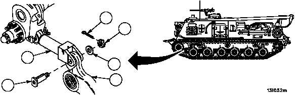
1. Remove cotter pin (1) from clevis pin (2). Discard cotter pin.
2. Remove nut (3), flat washer (4) and clevis pin (2) from adjusting link (5) and arm and hub assembly (6).
Figure 183A
1
2
3
4
5
ARMOR SKIRTS
REMOVED FOR CLARITY
6