TM 9--2350--292--20--2
0393 00--2
ADJUSTING LINK AND COMPONENTS REPAIR (NEW CONFIGURATION) –
CONTINUED
0393 00
Removal -- Continued
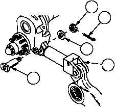
3. Remove cotter pin (7) from clevis pin (8). Discard cotter pin.
4. Remove nut (9), flat washer (10), clevis pin (8) and adjusting link (5) from vehicle.
Disassembly
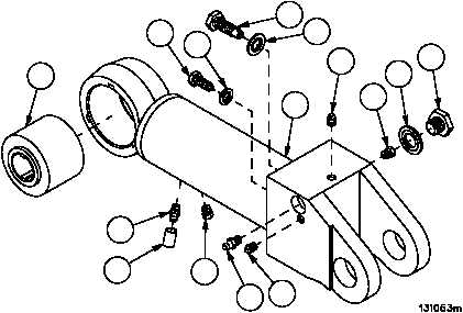
1. Remove two pipe plugs (11) from cylinder (12).
2. Remove grease bleed valve assembly (13) from cylinder (12). Discard preformed packing (14).
3. Remove pressure relief valve assembly (15) from cylinder (12). Discard preformed packing (16).
4. Remove plug (17) and safety relief valve (18) from cylinder (12). Discard preformed packing (19).
5. Remove lubrication fitting (20) from cylinder (12).
6. Remove sleeving insulation (21) and lubrication fitting (22) from cylinder (12). Discard sleeving insulation (21).
7. Remove safety relief valve (23) from cylinder (12).
CAUTION
All signs of previous stake positions on adjusting link
must be completely removed. Failure to comply could
result in improper bearing fit causing damage to bearing
and adjusting link.
8. Remove staked portion of adjusting link (5) that retains bearing (24).
9. Remove bearing (24) from adjusting link (5).
Figure 184A
7
8
9
10
5
24
13
14
15
16
12
11
18
19
17
11
20
23
21
22