TM 9--2350--292--20--2
0393 00--3
ADJUSTING LINK AND COMPONENTS REPAIR (NEW CONFIGURATION) –
CONTINUED
0393 00
Disassembly -- Continued
WARNING
10. Clean all parts with dry--cleaning solvent. Inspect parts for damage and replace as required.
Assembly.
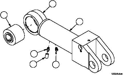
1. Install bearing (24) in adjusting link (5).
2. Stake bearing (24) in three equally spaced places on both sides of adjusting link (5).
3. Apply lubricant to threads of safety relief valve (23).
4. Install safety relief valve (23) in cylinder (12). Torque safety relief valve to 3--7 lb--ft (4.0--9.5 N•m).
5. Apply lubricant to threads of lubrication fitting (22).
6. Install lubrication fitting (22) in cylinder (12). Torque lubrication fitting to 6--8 lb--ft (8.1--10.8 N•m).
7. Cut new sleeving insulation (21) to 0.50 (12.7 mm).long.
8. Install sleeving insulation (21) over lubrication fitting (22). Heat shrink sleeving insulation (21) over lubrication fit-
ting (22). Do not cover hex portion of lubrication fitting (22).
Figure 184A
24
23
21
22
5
12