TM 9--2350--292--20--2
0452 00--1
DRAIN VALVES, CONTROLS AND RELATED PARTS REPLACEMENT
0452 00
THIS WORK PACKAGE COVERS:
Removal, Installation
INITIAL SETUP:
Tools and Special Tools
General mechanic’s tool kit (item 1, WP 0717 00)
Materials/Parts
Lockwashers (12) (item 52, WP 0718 00)
Lockwashers (14) (item 37, WP 0718 00)
Lockwashers (4) (item 9, WP 0718 00)
Cotter pins (4) (item 19, WP 0718 00)
Cotter pins (4) (item 53, WP 0718 00)
Cotter pins (2) (item 67, WP 0718 00)
Nonmetallic grommet (item 56, WP 0718 00)
Nonmetallic grommets (2) (item 55, WP 0718 00)
Preformed packings (2) (item 54, WP 0718 00)
Sealing compound (item 42, WP 0716 00)
Dry--cleaning solvent (item 1, WP 0716 00)
Equipment Conditions
Subfloor plates #13, #19 and #24 removed
(WP 0454 00)
For front and rear drain control assembly
Main winch and spade assembly removed
(WP 0497 00)
For front drain control assembly
Powerpack removed (WP 0188 00)
For rear drain control assembly
Storage rack assembly removed
(WP 0463 00)
For rear drain control assembly
Left air cleaner intake hoses and tube assemblies
removed (WP 0212 00)
For rear drain control assembly cable
NOTE
There are two drain valves and control assemblies. This
task replaces only the rear drain valve and control as-
sembly. Differences between front and rear drain valve
control assemblies are noted.
Perform only those steps required to complete repairs.
Removal
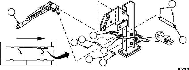
1. Remove two cotter pins (1) and two straight headed pins (2) securing two cable clevises (3) to lever (4). Discard
cotter pins.
2. Remove two cotter pins (5) and pin (6) from lever (4). Discard cotter pins.
FORWARD
1
1
2
2
3
3
4
5
6
FRONT
BULKHEAD
Figure 230


