TM 9--2350--292--20--2
0459 00--2
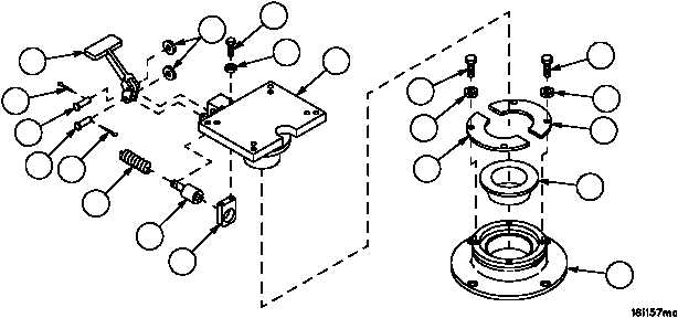
COMMANDER’S PEDESTAL REPAIR -- CONTINUED
0459 00
Disassembly--Continued
3. Remove two cotter pins (9), two flat washers (10), two clevis pins (11) and pedal (6) from base (5). Discard cotter
pins.
4. Remove two screws (12), two lockwashers (13), guide (14), spring (15) and lockpin (7) from base (5). Discard
lockwashers.
5. Remove bearing (16) from base (5).
6. Inspect parts for damage and replace as required.
Assembly
1. Install spring (15) and lockpin (7) in guide (14). Install guide (14) with lockpin (7) and spring (15) on base (5) with
two screws (12) and two new lockwashers (13).
2. Install pedal (6) on base (5) with two clevis pins (11), two flat washers (10) and two new cotter pins (9).
3. Install bearing (16) on base (5), then install base (5) in pedestal (4). Rotate base (5) until two retainers (3) can be
easily installed with mounting holes aligned. Secure two retainers (3) to pedestal (4) with four screws (1) and four
new lockwashers (2).
4. Make sure base (5) rotates freely on pedestal (4) and lockpin (7) engages locking slots of pedestal (4) when ped-
al (6) is depressed and released.
Figure 234
14
7
15
9
11
11
9
6
10
12
13
5
1
2
3
1
2
3
16
4
NOTE
FOLLOW--ON MAINTENANCE:
Install commander’s seat (WP 0457 00)
END OF TASK