TM 9--2350--292--20--2
0459 00--1
COMMANDER’S PEDESTAL REPAIR
0459 00
THIS WORK PACKAGE COVERS:
Disassembly, Assembly
INITIAL SETUP:
Tools and Special Tools
General mechanic’s tool kit (item 1, WP 0717 00)
Materials/Parts
Lockwashers (4) (item 62, WP 0718 00)
Cotter pins (2) (item 15, WP 0718 00)
Lockwashers (2) (item 115, WP 0718 00)
Equipment Conditions
Commander’s seat removed (WP 0457 00)
NOTE
Rotate base so that clearance notch (in base) permits
easy replacement of retainer screws.
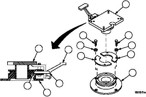
Disassembly
1. Remove four screws (1), four lockwashers (2) and two retainers (3) from pedestal (4). Discard lockwashers.
2. Rotate base (5) and depress pedal (6) until lockpin (7) is free of groove (8) while lifting base (5) off pedestal (4).
Figure 234
6
7
8
4
5
1
1
2
2
3
3
4
5