TM 9--2350--292--20--2
0355 00--4
BRAKE LINKAGE ALIGNMENT, ADJUSTMENT AND BLEEDING
(OLD CONFIGURATION) -- CONTINUED
0355 00
Alignment -- Continued
NOTE
Do not adjust linkage between modulating valve and
brake cylinder. This adjustment was made at the subas-
sembly level.
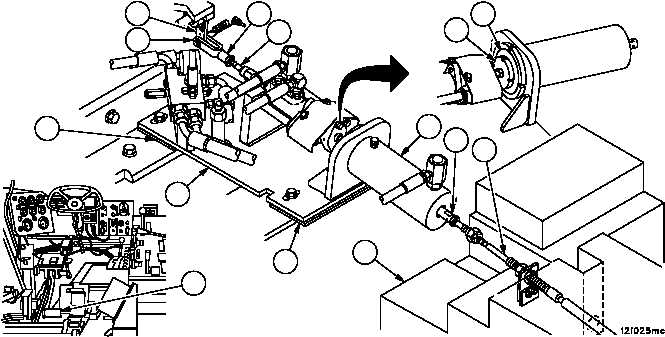
16. Ensure that disc (25) is resting against the face of brake cylinder (26), adjust rod assembly (18) until holes in lever
(19) and clevis (27) are aligned.
17. Connect rod assembly (18) to lever assembly (19) (WP 0366 00).
18. Release brake pedal (17) from steering wheel.
19. Remove screws securing plate assembly (28) to vehicle (WP 0374 00).
CAUTION
If shim stack is too high or too low, ball swivel may reach
the extent of its 10 percent misalignment capability and
introduce binding, causing equipment damage or failure.
20. Adjust height of the front of plate assembly (28) (remove or add plates (29) until linkage (30) moves freely without
binding).
21. Adjust height of the rear end of plate assembly (28) (remove or add plates (31) until the brake cable (2) is opti-
mized within the fuel tank (32) and rod assembly (33) is optimized in the center of hollow in brake cylinder (26)).
22. Secure plate assembly (28) to vehicle (WP 0374 00).
Figure 170
19
27
29
28
31
18
30
32
25
26
17
26
33
2