TM 9--2350--292--20--2
0355 00--2
BRAKE LINKAGE ALIGNMENT, ADJUSTMENT AND BLEEDING
(OLD CONFIGURATION) -- CONTINUED
0355 00
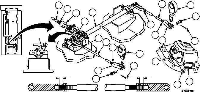
Alignment
1. Loosen nut (1) and disconnect brake cable assembly (2) from clevis (3).
2. Remove two cotter pins (4), two grooved head pins (5) and two rear brake rod assemblies (6) from two brake ap-
ply levers (7). Discard cotter pins.
3. Check both brake apply levers (7) to ensure that they are in the fully released position against their external stops
(8). If not fully released, push in on the adjustment screw collar (9) while turning the adjustment screw to position
the brake apply lever (7) against the stop (8).
4. Loosen four locking nuts (10) on two rear brake rod assemblies (6).
5. Insert a 1/8--inch locating pin at point 1.
WARNING
Adjustment to length of rod assemblies must be accom-
plished by adjusting both end clevises evenly. Rod end
clevises must maintain a minimum of 0.62 inch (15.7 mm)
thread engagement from end of rod assemblies at all
times. Failure to comply could result in rod assemblies
separation, causing loss of vehicle service brake, result-
ing in personnel injury or vehicle damage.
6. Adjust both ends of two rear brake rod assemblies (6) evenly until holes in clevis (11) align with holes in brake
apply levers (7) and long brake shaft (12) is lined up with short brake shaft (13). Verify thread engagement of
0.62 inch (15.7 mm) exists between face of locking nut and end of rod assemblies.
7. Connect two rear brake rod assemblies (6) to two brake apply levers (7) with two grooved head pins (5) and two
new cotter pins (4).
8. Tighten four locking nuts (10) and remove 1/8--inch locating pin from point 1.
Figure 169
3
2
1
FORWARD
POINT 1
10
6
7
5
10
4
11
7
4
6
10
5
11
10
7
8
9
13
12
0.62 IN
(15.7 MM)
0.62 IN
(15.7 MM)