TM 5-4270-501-14&P
STARTERS
Nicad System
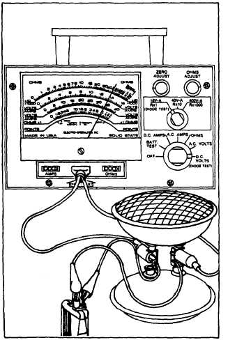
Fig. 51 - Battery Charger Tester
A fully charged battery, when connected to this headlight
set up will light the bulbs brightly for at least five minutes.
The voltmeter reading should be 13.5 volts minimum
after one minute, using the headlight load. A voltmeter
reading of 13 volts, or less, within a one minute period
indicates a defective cell in the battery. Replace battery.
NOTE: The battery must be in a fully charged condition,
prior to the above test. If the battery is not fully charged,
it will require charging for a 14 to 16 hour period before
proceeding with the above test. This voltmeter test is
valid only after a one minute period, when using the
lights as a load, because the voltage continues to drop
slowly throughout most of the test.
BATTERY CHARGER TESTER
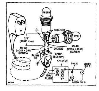
The parts needed to construct a battery charger tester
are as follows. (See following for parts ordering
information.)
1.
One IN4005 diode.
2.
Two lamp sockets, such as a Dialco #0931-102,
red color and a #0932-102, green color.
3.
Two #53 bulbs.
4.
One #6-32, 3/4" long screw (m3.5 x 0.6).
5.
One #3-48, 3/4" long screw (m2.5 x 0.45).
These components are soldered together as shown in
the accompanying illustration, Fig. 52. if desired, these
components may be fitted to a plastic case.
The test procedure is as follows:
Plug the charger into a 120 volt AC outlet, known to be
good, connect the other end of the charger to the tester.
A charger in good condition will light the green bulb only.
If neither bulb lights, or both bulbs light, the charger
would be defective.
NOTE: The component parts for this tester may be
purchased at any radio supply parts house.
Fig. 52 - Battery Tester
KEY SWITCH TEST
The equipment needed to test the key switch is as
follows: Briggs & Stratton meter #19236 or equivalent
ohmmeter.
Test key switch as noted in Fig. 53. Replace switch if
not as shown under column, "Check Continuity."
12


