TM 5-4240-501-14&P
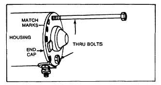
Fig. 75 - Removing Thru Bolts
CAUTION: Do not clamp the motor housing in a vise or
strike the motor housing with a hammer. These motors
contain two powerful ceramic magnets which can be
broken or cracked if the motor housing. is deformed or
dented.
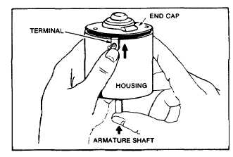
Remove armature and end cap as shown in Fig. 76. (If
120 volt motor, remove ground post with 1/4" nut driver
to free rectifier assembly. Fig. 79.)
Fig. 76 - Removing Armature
Clean all dirt or corrosion accumulations from the
armature, end cap, end head, etc. The bearings, motor
housing and armature should not be soaked in a
cleaning solution. The armature commutator may be
cleaned with a fine sand paper or commutator paper. Do
not use emery cloth, as emery will embed in the
commutator and cause rapid brush wear. If it is
suspected that the armature is defective, a new armature
should be tried in the motor. If proper testing equipment
is available, check the suspected armature to determine
if it is defective.
Starter motor armatures have very low resistance,
usually below detection on available multimeters (volt -
ampere - ohm). To check for shorted armatures, a piece
of equipment known as a "growler" may be used.
STARTERS
Gear Drive 12V & 120V
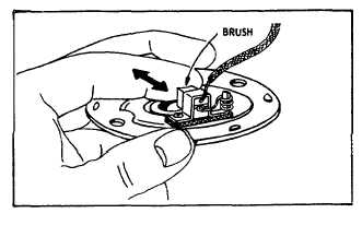
The brushes should be checked for poor seating, weak
brush springs, dirt, oil or corrosion. See Fig. 77.
If the magnets are suspect, a new motor housing should
be tried to test motor performance (Figs. 72 and 73).
Fig. 77 - Check Brushes
CHECKING THE RECTIFIER ASSEMBLY 120 VAC
STARTER MOTOR
Disconnect rectifier from end cap by removing leads
from terminals.
Test rectifier with multimeter (VOA meter, page 8) set on
resistance (R x 1 ohm) scale. Touch meter leads to red
and black rectifier lead, then reverse meter leads and
recheck. The meter should indicate a reading in one
direction only. Touch meter leads to black rectifier lead
shown in Fig. 79 and both AC posts, then reverse meter
leads. The meter should show a reading in one direction
only. Touch meter leads to red rectifier lead and both
AC posts. then reverse meter leads. The meter should
show a reading in one direction only.
If a meter reading is indicated in both directions or no
reading is indicated in either direction, the rectifier
assembly is defective and must be replaced.
ASSEMBLY OF STARTER MOTORS
When all parts have been thoroughly inspected, lightly
lubricate the bearings with #20 oil, and reassemble in the
following manner.
Insert the brushes in their respective holders. NOTE: A
tool such as shown in Fig. 45 and 78 should be used to
hold the brushes clear of the armature commutator when
assembling the armature to end cap.
21