TM 5-4240-501-14&P
STARTERS-Briggs & Stratton
Gear Drive 12V & 120V
CAUTION: DO NOT clamp motor housing in a vise or
strike with a steel hammer. Starter motors contain two
powerful magnets which can be broken or cracked if the
motor housing is deformed or dented.
Activate the starter motor and note readings of ammeter
and tachometer (RPM). Note length of starter motor
housing as shown on page 9 and refer to Fig. 91. A
starter
motor
in
good
condition
will
be
within
specifications listed.
Motor Housing
Minimum
Maximum
Length
Motor RPM
Amperes
3-1/16" (77.8 mm)
6500
18
3-3/4" (95.3 mm)
6900
19
Fig. 91 - 12 Volt DC Starter Motor Specifications
120 VOLT AC STARTER MOTOR
Connect the starter motor and ammeter as shown in Fig.
92.
DANGER: It is recommended that the starter motor be
Hi-Pot tested after final re-assembly.
CAUTION: The performance test of this starter requires
the use of an ammeter, connected in the 120 volt AC line
cord. Extreme care should be used in making this test to
minimize the hazard of electrical shock.
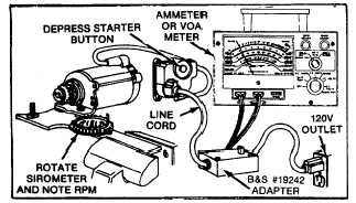
Fig. 92 - Checking Starter Motor Performance
Plug the electrical cord into a 120 volt outlet and press
the starter motor button. Note the readings of
tachometer or sirometer (RPM) and ammeter. A starter
motor in good condition will be within the following
specifications. Fig. 93.
Motor Housing
Minimum
Maximum
Length
RPM
Amperes
3-1/2" (88.9 mm)
6500
2.7
Fig. 93 - Starter Motor Specifications
If either the 120 VAC or 12 VDC starter motor does not
perform satisfactorily, the following should be checked
and corrected if necessary.
1.
A binding or seizing condition in the starter motor
bearings.
2.
Starter motor brushes sticking in brush holders.
3.
A dirty or worn armature commutator or brushes.
4.
A shorted, open or grounded armature.
A.
Shorted armature (wire insulation worn and
wires touching one another). Will be indicated
by low or no R.P.M.
B.
Open armature (wire broken) will be indicated
by low or no RPM.
C.
Grounded armature (wire insulation worn and
wire touching armature lamination or shaft).
Will be indicated by excessive current or no
RPM.
5.
A defective starter motor switch.
6.
A defective starter motor rectifier assembly. (120
volt AC only).
7.
Weakened magnets.
DISASSEMBLY OF STARTER MOTORS
Study Fig. 84 prior to starter motor disassembly.
Remove thru bolts. The drive head end may now be
removed. Inspect bushing for wear. If worn, replace
drive head end assembly. Fig. 94.
NOTE: MATCH MARKS AND THRU BOLTS MUST BE
PLACED
IN
THE
SAME
POSITION
AS
WHEN
RELMVOVED OR INTERFERENCE MAY RESULT.
(See checking starter motor drive if repair, cleaning or
replacement of drive assembly is necessary.)
Fig. 94 - Removing Thru Bolts
26