TM 5-4240-501-14&P
STARTERS- Briggs & Stratton Gear Drive 12V & 120V
Equipment Needed -
1.
An AC volt meter capable of measuring 120
volts AC.
2.
An AC ammeter capable of measuring 25
amperes AC.
3.
A VOA meter as shown on page 20 may be
used in place of volt meter and ammeter noted above.
4.
Remove the spark plug from the engine.
CAUTION: The test of this rectifier assembly requires the
use of a 120 volt AC circuit. Extreme care should be
used when making this test to minimize the hazard of
electrical shock.
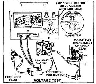
Measure the line voltage of the 120 volt AC outlet to be
used. Connect the voltmeter and ammeter as shown in
Fig. 99 prior to removal from engine.
Fig. 99 - Checking Control Assembly Performance
A control assembly in good condition will show 120 volts
of line voltage and a maximum of 15 amperes on the
ammeter with starter button depressed and starter motor
engaged. Fig. 99 inset.
If meters show no readings or a reading of 20 amperes
is exceeded, see Troubleshooting, page 9 and 10.
DISASSEMBLING CONTROL ASSEMBLY
DANGER: Disconnect extension cord from outlet before
disassembling control assembly.
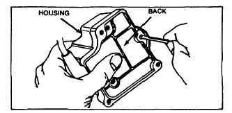
With control assembly removed from mounting surface,
remove three screws holding back plate to housing. Fig.
100. Note position of wires.
Fig. 100 - Removing Back Plate
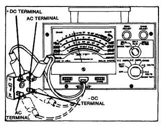
Disconnect wires from rectifier.. Test rectifier as shown
in Fig. 101. With one probe on (+) plus terminal, touch
three remaining terminals with other probe. Reverse
procedure. Place other probe on (+) terminal and touch
three terminals with probe. One test should not indicate
any reading.
Fig. 101 - Checking Rectifier
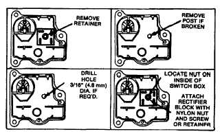
To replace rectifier assembly, remove retainer spring
washer. Note rectifier position and remove. If rectifier
post should break, drill a 3/16" diameter hole in post
location. Connect rectifier with plastic screw and nut.
Assemble as noted in Fig. 102 and 104.
Fig. 102 - Replacing Rectifier
28