TM 5-4240-501-14&P
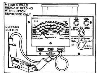
Test switch assembly as noted in Fig. 103.
Fig. 103 - Testing Switch Assembly
When re-assembling switch, position starter button and
return spring as noted in Fig. 98.
The cord assembly continuity may be tested with the
VOA meter noted on page 8.
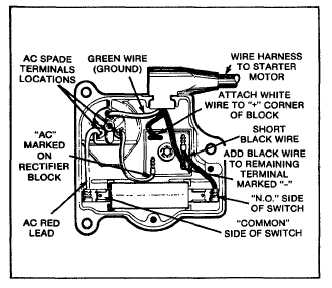
ASSEMBLY OF 120 VOLT CONTROL ASSEMBLY
Connect wires as shown in Fig. 104. CAUTION:
Incorrect assembly of black and white wires from cord to
rectifier will cause motor to run backwards.
Fig. 104 - Wiring Diagram
Re-assemble backplate to housing. Fig. 100.
Briggs & Stratton- STARTERS
Gear Drive 12V & 120V
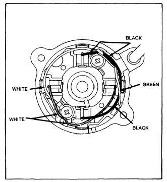
ASSEMBLY OF STATOR MOTOR
When all parts have been thoroughly inspected, lightly
lubricate the bearings with #20 oil and reassemble in the
following manner. (Assemble wiring in commutator end
cap as shown in Fig. 105, 120 volt AC.)
Fig. 105 - Commutator End Cap Wiring 120 Volt AC
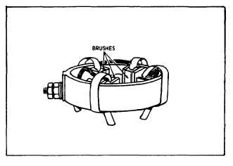
Insert brushes and springs in their respective holders.
NOTE: A tool as shown in Fig. 45 and 106 should be
used to hold the brushes clear of the armature
commutator during assembly.
Fig. 106 - Positioning Brushes
29