TM 5-4240-501-14&P
STARTERS
Gear Drive 12V & 120V
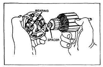
Fig. 107 - Assembling Armature to End Cap
Slide motor housing over armature with the notch toward
commutator end cap. Match alignment marks. Fig. 94.
Care should be used to prevent damage to magnets in
motor housing during assembly. Assemble spacers and
drive head end bracket, again aligning match marks.
Armature end play is .006 to .038" (.15 to .97 mm) after
assembly.
Assemble thru bolts and washers. Torque thru bolts, 45
to 55 inch pounds (5.1 to 6.2 Nm) for 1/4- 20 thru bolts
and 40 to 45 inch pounds (4.5 to 5.1 Nm) for 10-24 thru
bolts.
HIGH POTENTIAL (HI-POT) TEST -
120 VAC (ONLY)
Before anc after repairing the 120 volt AC starter motor,
a Hi-Pot test must be made to prevent injury. If the
proper test equipment is not available, take the starter
motor to a qualified electric motor repair shop for testing.
After assembly of the starter motor drive and Hi-Pot test
is passed, the starter motor is now ready for installation
to the engine.
GEAR DRIVE STARTERS
120 VOLT AC; 12 VOLT DC
STARTER MOTOR - USED ON SERIES
140000, 170000 and 190000
These starter motors use a gear type engagement
method, similar to an automobile starter. When the
starter motor is activated, the helix on the starter motor
shaft drives a pinion gear into engagement with a ring
gear attached to the engine flywheel and cranks the
engine.
Electrical shock is always a hazard with any electrical
equipment. To minimize the hazard of electrical shock,
the 120 volt starter motor is provided with a three wire
power source connection. To maintain the safety
provided against electrical shock, the extension cord
used between the starter motor and the power source
must be a three wire cord, which connects to a properly
grounded receptacle. DO NOT USE power cords longer
than 25 feet.
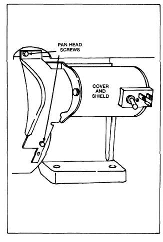
Fig. 108 - 120 Volt Gear Drive Starter Motor
CAUTION: DO NOT run starter motor for more than one
minute without cooling 15 minutes.
It is recommended a battery of 32 ampere hour capacity
be used with the 12 volt starter. The battery cable size
should be #4 or #6. Note: A battery of higher amperage
may be required for extremely cold weather starting
conditions.
Replacing a Ring Gear
To replace a worn or damaged flywheel ring gear, see
page 23, Fig. 82.
30


